K R A ME R E LE CT R O N IC S L T D .
This page is intentionally left blank
Contents 1 Introduction 1 2 2.1 Getting Started Achieving the Best Performance 2 2 3 Overview 3 4 Your SPK-C613 5 5.1 5.2 5.3 5.4 5.
This page is intentionally left blank
1 Introduction Welcome to Kramer Electronics! Since 1981, Kramer Electronics has been providing a world of unique, creative, and affordable solutions to the vast range of problems that confront video, audio, presentation, and broadcasting professionals on a daily basis.
2 Getting Started We recommend that you: Unpack the equipment carefully and save the original box and packaging • materials for possible future shipment • Review the contents of this user manual • Use Kramer high-performance high-resolution cables i 2.1 Go to http://www.kramerelectronics.com to check for up-to-date user manuals, application programs, and to check if firmware upgrades are available (where appropriate).
3 Overview The SPK-C613 speakers include a pair of high performance Open-back Ceiling speakers that can be mounted on the ceiling. The optional Kramer Suspended Ceiling Speaker Mounting Kit (SKIC) can safely secure the speakers to the ceiling as well. The SPK-C613 speakers feature a multi tap power transformer for selecting 8Ω (bypassing the transformer) or 70V/100V power settings suitable for array installation.
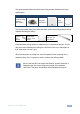
4 Your SPK-C613 Figure 2 defines the SPK-C613: Figure 2: SPK-C613 Open-back Ceiling Speakers The speaker black and red stereo sockets connect to the black and red sockets of the amplifier (see the wiring example in Figure 9).
The following table defines the Open-back ceiling speaker hardware items (per speaker pair): Description A pair of ceiling speakers (one shown) Two grilles (one shown) Cutout template The following table defines the items that make up the optional Suspended Ceiling Speaker Mounting Kit (SKIC): Four support ring screws Two ceiling support rings (C-ring) – (one shown) Two pairs of tile rails (one of a pair shown) Each Open-back ceiling speaker is supported by a C-ring and two tile rails.
5 Installing the Open-back Ceiling Speakers This section explains how to install the Open-back ceiling speakers, that is: 5.1 • Choosing the best place to locate your speakers (see Section 5.1) • Cutting the ceiling tile (see Section 5.2) • Installing the speakers (see Section 5.3) • Array installation general guidelines (see Section 5.4) • Painting the speakers (see Section 5.5) Choosing the Best Location Ideally, locate the speakers above the main listening area.
! Do not nail or staple the speaker wires. If you are mounting the speakers onto a ceiling tile, remove the ceiling tiles where you plan to install the speakers. Use the template to trace and then cutout the speaker hole over an empty box. The open-back ceiling speakers are supported by the ceiling mounting kit (two C-rings and two pairs of tile rails. The tile rails prevent the speakers from falling if the tile itself comes out or falls apart, as their ends catch onto the T-grid).
3. Adjust each speaker to the appropriate tap setting before installing the grille (see Figure 4). Set the tap according to the power requirements of the speaker based on its location in the room (for example, a speaker located in a remote corner would require additional power) Figure 4: Adjust Tap Selector ! For 100V installations, DO NOT set the tapping switch beyond 30W. Doing so may cause damage to both the speaker and the amplifier. 4.
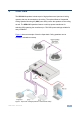
T-channel Grid C-ring Support Ring Screws Ceiling Tile Tile Rails Figure 5: Installing the Open-back Ceiling Speakers 2. Place the tile rails on the tile and snap them into the two tabs on the C-ring. Align the rails so that the ends extend over the T-channel grid. 3. Insert a screw through each tab on the C-ring to secure the rails. 4. Connect the speaker wires to the speaker terminals. 5. Insert the speaker into the opening and tighten the screws.
Figure 6: The Speaker Coverage Area The coverage angle of the speaker determines the coverage area and the number of speakers required in the array installation. Two patterns are usually used for array installations, square (see Figure 7) or hexagonal (see Figure 8), depending on the shape of the installation area. The speakers are positioned according to their coverage area.
Figure 9 shows an example of parallel wiring in a square array installation: Figure 9: Square Layout Parallel Wiring SPK-C613 - Installing the Open-back Ceiling Speakers 11
5.5 Painting the Speaker You can paint the speakers before or after the speakers are installed. When painting before installation: Clean the rim and grille with mineral spirits or other light solvent that is • unlikely to damage the surface Spray with color by holding the spray can at an angle of 45° • i When spraying the grille, take care not to clog the holes in the grille as this will greatly reduce the sound quality of the speakers.
6 Technical Specifications Audio and Power DESCRIPTION: 2-way open ceiling speakers HIGH FREQUENCY DRIVER: 1/2" MYLAR dome tweeter LOW FREQUENCY DRIVER: 6.5” Polypropylene cone with rubber edge woofer IMPEDANCE: 8Ω DISPERSION COVERAGE: 120° @2000Hz CROSSOVER FREQUENCY: 3kHz NOMINAL SENSITIVITY: 84dB SPL @1m, 1W DIRECTIVITY FACTOR (Q): 5.1 (averaged 100Hz – 10kHz); 6.2 (2kHz) DIRECTIVITY INDEX (DI): 6.8dB (averaged 100Hz – 10kHz); 5.
This page is intentionally left blank
For the latest information on our products and a list of Kramer distributors, visit our Web site where updates to this user manual may be found. We welcome your questions, comments, and feedback. Web site: www.kramerelectronics.com E-mail: info@kramerel.