Kramer Electronics, Ltd.
Contents Contents 1 2 2.1 3 3.1 3.2 4 4.1 Introduction Getting Started Quick Start Overview Shielded Twisted Pair (STP) / Unshielded Twisted Pair (UTP) Recommendations for Achieving the Best Performance Your TP-125 / TP-126 Your TP-125 UXGA / Audio / Data Line Transmitter 1 1 2 3 3 4 4 5 4.1.1 The TP-125 Internal Polarity Switches 6 4.2 Your TP-126 UXGA / Audio / Data Line Receiver 7 4.2.1 Your TP-126 UXGA / Audio / Data Line Receiver (Underside) 8 5 5.1 5.
Introduction 1 Introduction Welcome to Kramer Electronics! Since 1981, Kramer Electronics has been providing a world of unique, creative, and affordable solutions to the vast range of problems that confront the video, audio, presentation, and broadcasting professional on a daily basis. In recent years, we have redesigned and upgraded most of our line, making the best even better! Our 1,000-plus different models now appear in 11 groups1 that are clearly defined by function.
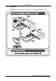
Getting Started 2.1 Quick Start This quick start chart summarizes the basic setup and operation steps.
Overview 3 Overview The TP-125 and TP-126 are a high-performance twisted pair transmitter and receiver for computer graphics video (including HDTV), unbalanced stereo audio, and RS-232 control commands. The TP-125 converts computer graphics video, unbalanced stereo analog audio, and RS-232 control commands to a twisted pair signal, and the TP-126 converts the twisted pair signal back into computer graphics video, unbalanced stereo and S/PDIF digital audio, and RS-232 control signals.
Your TP-125 / TP-126 is preferred. However, unshielded twisted pair (UTP) cable should be installed far away from sources of electromagnetic interference such as electric cables and motors. It is recommended to use shielded twisted pair (STP) skew-free Kramer cable BC-SXTP for transmitting VGA signals, and shielded twisted pair (STP) non-skew-free Kramer BC-STP cable for digital signals. 3.
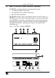
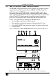
Your TP-125 / TP-126 4.1 Your TP-125 UXGA / Audio / Data Line Transmitter The TP-125 is a high-performance transmitter that accepts: A computer graphics input signal An unbalanced stereo analog audio signal RS-232 control commands The TP-125 codes the signals and transmits them over CAT 5 cable to a TP-126 receiver. The stereo analog audio signal is converted to the digital audio (S/PDIF) stream before transmitting, thus preserving the quality of the audio source signals.
Your TP-125 / TP-126 Table 1: TP-125 UXGA / Audio / Data Line Transmitter Features 1 2 3 4 # Feature 12V DC AUDIO IN 3.5mm Mini Jack RS-232 Terminal Block Connector LINE OUT RJ-45 Connector 5 6 UXGA IN 15-pin HD (F) Connector ON LED Function +12V DC connector for powering the unit Connects to the audio source Connects to the PC or the Remote Controller (see section 5.
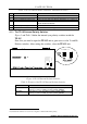
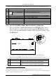
Your TP-125 / TP-126 4.2 Your TP-126 UXGA / Audio / Data Line Receiver The TP-126 is a high-performance receiver obtaining the computer graphics signal/audio/control data from the Kramer TP-125 via UTP cabling at its CAT 5 line input. The TP-126 outputs a computer graphics signal, an unbalanced stereo analog audio signal, a converted digital audio (S/PDIF) signal, and bi-directional RS-232 control commands and data, to and from the receiver.
Your TP-125 / TP-126 Table 3: TP-126 UXGA / Audio / Data Line Receiver (Top, Front, and Rear) Features # Feature 12V DC 4 5 6 7 8 9 10 RS-232 Terminal Block Connector LINE IN RJ-45 Connector UXGA OUT 15-pin HD (F) Connector ON LED 2 EQ. Trimmer LEVEL Trimmer LINK LED AUDIO OUT 1 2 3 S/PDIF RCA connector ANALOG 3.
Connecting the TP-125/TP-126 Transmitter/Receiver Pair 5 Connecting the TP-125/TP-126 Transmitter/Receiver Pair You can use the TP-125 UXGA / Audio / Data Line Transmitter and the TP-126 UXGA / Audio / Data Line Receiver to configure a twisted pair transmitter and receiver system, to transmit the video, audio and RS-232 control signals via CAT 5 UTP cable.
Connecting the TP-125/TP-126 Transmitter/Receiver Pair If necessary, set the H SYNC and V SYNC switches1, on the underside Figure 5: Connecting the UXGA / Audio / Data Line Transmitter / Receiver System 1 By default, both switches are set down (for negative V SYNC and H SYNC polarity) 10 KRAMER: SIMPLE CREATIVE TECHNOLOGY
Connecting the TP-125/TP-126 Transmitter/Receiver Pair 5.1 Transmitting via RS-232 (for example, using a PC) Prepare an RS-232 cable with a 9-pin D-sub connector at one end, and a 3 PIN terminal block connector at the other end, as defined in Table 5 and Figure 6: Table 5: RS-232 PINOUT Connection Connect this PIN on the Terminal Block Connector: To this PIN on the 9-pin D-sub Connector TxD PIN 2 RxD PIN 3 GND PIN 5 Figure 6: RS-232 PINOUT Connection 5.
Technical Specifications 6 Technical Specifications The TP-125, TP-126 technical specifications are shown in Table 7: Table 7: Technical Specifications of the TP-125 / TP-126 INPUTS: OUTPUTS: TP-125 Video: 1 UXGA on an HD15 connector Audio: 1 audio ANALOG 3.5mm mini jack 1 RJ-45 OUT connector RESOLUTION: Up to UXGA or 1920x1200 MAX. OUTPUT LEVEL: TP-126 1 RJ-45 LINE IN connector Video: 1 UXGA on an HD15 connector Audio: 1 audio S/PDIF RCA connector 1 audio ANALOG 3.5mm mini jack Video: 1.6V Audio: 2.
13
For the latest information on our products and a list of Kramer distributors, visit our Web site: www.kramerelectronics.com where updates to this user manual may be found. We welcome your questions, comments and feedback. Safety Warning: Disconnect the unit from the power supply before opening/servicing. Caution P/N: 2900- 000371 Rev: 4 Kramer Electronics, Ltd. Web site: www.kramerelectronics.com E-mail: info@kramerel.