KRAMER ELECTRONICS, Ltd.
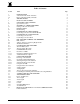
Table of Contents Section .1 .1.1 .1.2 .
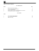
Table of Contents (Continued) List of Illustrations Figure Page RS-232 Control Connector Wiring VS-1211/1201 Front/Rear Panel Features Location of Internal Jumpers VS-Series Remote Connector Socket and Balanced Audio Pinout Connecting Two Switchers to add Outputs 8 9 3 5 8 List of Tables Table VS-1211/1201 Front Panel Features VS-1211/1201 Rear Panel Features DIP Switch Settings KRAMER ELECTRONICS LTD.
1. INTRODUCTION Congratulations on your purchase of this Kramer Electronics switcher. Since 1981 Kramer has been dedicated to the development and manufacture of high quality video/audio equipment. The Kramer industrial line has become an integral part of many of the best video/audio production and presentation facilities around the world. In recent years, Kramer has redesigned and upgraded most of the industrial line, making the best even better.
All the models can be interconnected in a variety of ways. For example, two VS-1211 units become 24x1 or 12x2, etc. Three or four VS-1211 units, depending on whether the system is RGB or RGBS, become a 12x1 video component switcher. Finally, the video signal bandwidth is 225MHz (typical), which permits the switchers to be used in the most demanding applications. 1.
2. SPECIFICATIONS Models VS-1211, VS-1011, VS-811, VS-611, VS-411, VS-1201xl, VS-1001xlm, VS-801xlm, VS601xlm, VS-401xlm Inputs 12, 10, 8, 6, 4 video - composite/single component, 1Vpp/75ohm on BNC connectors. 12, 10, 8, 6, 4 balanced/unbalanced audio, +4dBm/10kohm, on 2-part, snap fit terminal blocks (for the "11" group only), or RCA connectors (for the "01xl/m" group only). One external sync input (or composite video) 1Vpp/75ohm, on BNC connector.
3. HOW DO I GET STARTED? The fastest way to get started is to take your time and do everything right the first time. Taking 15 minutes to read this manual may save you a few hours later. You don’t even have to read the whole manual. At the beginning of each section, you’ll find an overview of the section. So if the section doesn’t apply to you, you don’t have to spend your time reading it. 4. UNPACKING AND CONTENTS The items contained in your Kramer VS switcher package are listed below.
5. KRAMER “VS” SERIES SWITCHERS This section shows you all of the controls and connections of your switcher. Understanding all of the controls and connections helps you realize its full power. All the switchers described in this manual are equipped with RS-232 Connectors (for PC control) and the connector wiring is described in Figure 1.
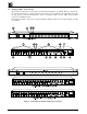
5.1 Getting to Know Your Switcher Most front/rear panel features of the switchers described in this manual are very similar. Therefore, only the VS1211 and the VS-1201xl are described and they represent the rest of the switchers. The main difference is that the “11” group has snap fit terminal block connectors for balanced audio and the “01xl” group has RCA connectors for unbalanced audio.
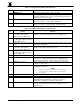
Table : VS-1211/1201/1001xlm Front Panel Features No. Feature Function 1. 2. POWER Switch INPUT SELECTOR pushbuttons 3. Internal cable EQ. trimmer 4. Internal LEVEL trimmer Illuminated switch: Supplies power to the unit. Each input may be selected by the corresponding input select button. The buttons illuminate when pressed and the illuminated input select button identifies the active input. Internally located and accessed through hole in the switcher base.
6. INSTALLATION 6.1 Rackmounting Each of the amplifiers included in this manual may be rackmounted in a standard 19” (1U) EIA rack assembly and includes rack “ ears” at the ends of the front panel. (The optional VS-2000 controller requires 2U of rack height, at 3.5".) These devices do not require any specific spacing above or below the unit for ventilation.
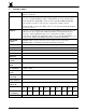
Table : DIP Switch Settings Switcher # Machine 1 (Master) Machine 2 (Slave) Machine 3 (Slave) Machine 4 (Slave) Machine 5 (Slave) Machine 6 (Slave) Machine 7 (Slave) Machine 8 (Slave) 1 (Reply) ON ON or OFF ON or OFF ON or OFF ON or OFF ON or OFF ON or OFF ON or OFF DIP Switch # 2 3 ON ON ON ON ON OFF ON OFF OFF ON OFF ON OFF OFF OFF OFF 4 ON OFF ON OFF ON OFF ON OFF NOTE The Slave "Reply" settings are all ON or all OFF, depending on the requirements of the system (see detailed configuration in section
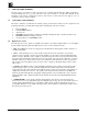
Figure : Location of Internal Jumpers KRAMER ELECTRONICS LTD.
9.3 The Internal Trimmers The trimmers are internally located and are accessed through holes in the switcher base (see section 14.2 “ Weak Switcher Video Signals” ). These allow you, if necessary, to adjust the switcher output signal level and cable compensation. 10. CONTROLLING THE SWITCHER The VS-1211/411 and VS-1201xl/401xlm switcher families can be controlled by the following methods: By touch buttons on the front panel (see section 12.2 "Operating an Individual Switcher").
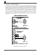
Figure : VS-Series Remote Connector Socket and Balanced Audio Pinout KRAMER ELECTRONICS LTD.
11. CONNECTING TO A PC To connect directly to a PC without using the KRAMER Null-Modem Adapter, make connections as in Figure 1. To use the KRAMER Adapter instead (recommended), plug one end into the PC' s serial port, then connect from the other end to the switcher using a 9-pin flat-cable. Alternatively, connect only pins 2, 3, and 5 from the Adapter to the switcher (one-to-one connection). 11.
12.2.1 Selecting an Input on the Switchers Input selection on the switchers described in this manual is simply made by pressing buttons marked “ 1” , “ 2” etc. on the front panel, or by operating your preferred remote device (see "KRAMER Switcher Remote Control Options"). These buttons correspond to the input connections as marked on the back panel. 12.2.2 Selecting the Proper Sync Format The Sync will be provided from an external video source.
3. 4. 5. 6. 7. 8. Connect the output from video source #1 to the first switcher input #1, then to the second switcher input #1 using a T or Y connector. Repeat for source #2 and input #2, etc. Connect one acceptor to the output of one switcher and another acceptor to the output of the other switcher. You now have a twelve input switcher complex with two outputs. You can continue to expand the number of outputs by adding a third switcher, etc., to obtain a 12x3 switcher, etc.
7. For RS-232 control of the system, connect the PC to the Master switcher via the null modem adapter. Each switcher in the configuration should be allocated a unique machine number and the "Reply" option should be to “ ON” (see Table 3, "Table of DIP Switch Settings"). The system may also be controlled via RS-485. 8. Connect the sources to the appropriate switcher inputs. 9. Connect the power cable of each switcher to the mains supply and turn ON each switcher. 10. You now have a 24 or 36, etc.
14.1 Power and Indicators Problem Remedy 1. No Power 2. 3. Confirm that the rocker switch is in the “ ON” position, and that the lamp is illuminated. Confirm that power connections are secured at the amplifier and at the receptacle. Make sure the receptacle is active, outputting the proper mains voltage. If there is still no power, check the fuse.
Problem Remedy Noise bars are “ rolling” up or down in the output image Hum bars (ground loop) are caused by a difference in the ground potential of any two or more devices connected to your signal path. This difference is compensated by passing that voltage difference through any available interconnection, including your video cables.
14.4 Software Problem Software version is not updated Remedy Carefully remove the switcher cover and identify the EPROM chip that is located in the middle of the main board, marked by a white sticker. Remove the chip with the proper tools and insert the new EPROM carefully, observing proper polarity. 14.5 Control Problem No control of switcher from VS2000 control panel Remedy 3. 4. 5. 6. 7. No control of switcher from PC software 1. 2. 3. 4. 5. 6. 7.
14.7 Vertical Interval Problem Remedy The switcher is switching, but there are transitional effects when using genlocked sources. The picture jumps and rolls, and the color is lost until the acceptor (a VCR, for example) has readjusted itself to the new color information. There is no vertical interval Sync source for switching. It should be available either on video input #1 or on an external genlocked source as a live video or a live black burst signal. Which one, will depend on certain jumper settings.
LIMITED WARRANTY Kramer Electronics (hereafter Kramer) warrants this product to be free from defects in material and workmanship under the following terms. HOW LONG IS THE WARRANTY Labor and parts are warranted for three year from the date of the first customer purchase. WHO IS PROTECTED Only the first purchase customer may enforce this warranty. WHAT IS COVERED AND WHAT IS NOT COVERED Except as below, this warranty covers all defects in material or workmanship in this product.
LIMITATION OF IMPLIED WARRANTIES All implied warranties, including warranties of merchantability and fitness for a particular purpose, are limited in duration to the length of this warranty. EXCLUSION OF DAMAGES Kramer’ s liability for any defective products is limited to the repair or replacement of the product at our option. Kramer shall not be liable for: 1. 2.
For the latest information on our products and a list of Kramer distributors, visit our Web site: www.kramerelectronics.com. Updates to this user manual may be found at http://www.kramerelectronics.com/manuals.html. We welcome your questions, comments and feedback. Kramer Electronics, Ltd. Web site: www.kramerelectronics.com E-mail: info@kramerel.