Kramer Electronics, Ltd.
Contents Contents 1 2 2.1 3 3.1 3.2 3.3 3.4 3.5 3.6 4 4.1 4.2 4.3 5 5.1 5.2 5.3 5.4 5.5 5.6 5.
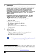
Introduction 1 Introduction Welcome to Kramer Electronics! Since 1981, Kramer Electronics has been providing a world of unique, creative, and affordable solutions to the vast range of problems that confront the video, audio, presentation, and broadcasting professional on a daily basis. In recent years, we have redesigned and upgraded most of our line, making the best even better! Our 1,000-plus different models now appear in 11 groups1 that are clearly defined by function.
Getting Started 2.1 Quick Start This quick start chart summarizes the basic setup and operation steps.
Overview 3 Overview The TP-582T and TP-582R are a high-quality twisted pair transmitter and receiver for HDMI, 100BaseT Ethernet, bidirectional RS-232 and IR signals. With the TP-582T you can select one of two HDMI inputs, and convert it with the 100BaseT Ethernet, RS-232 and IR input signals to a twisted pair signal. The TP-582R converts the twisted pair signal back to 100BaseT Ethernet, RS-232, IR and two HDMI outputs, and de-embeds the audio to S/PDIF and TOSLINK® audio outputs.
Overview The compact MegaTOOLS® enclosures (for the transmitters and the receiver) let you rack mount up to two units side-by-side in a 1U 19” rack space when using the optional RK-T2B rack.
Overview 3.
Your HDMI Line Transmitters/Receiver 4 Your HDMI Line Transmitters/Receiver This section describes the: TP-581T HDMI Line Transmitter, see Section 4.1 TP-582T HDMI Switcher/Line Transmitter, see Section 4.2 TP-582R HDMI Line Receiver DA, see Section 4.3 4.
Your HDMI Line Transmitters/Receiver 4.2 Your TP-582T HDMI Switcher/Line Transmitter Figure 2 and Table 2 define the TP-582T: Figure 2: TP-582T HDMI Switcher/Line Transmitter Table 2: TP-582T HDMI Switcher/Line Transmitter Features # 1 2 3 4 5 6 7 8 9 10 11 12 13 14 15 16 Feature LINE OUT RJ-45 Connector HDMI IN 1 Connector HDMI IN 2 Connector IR 3.
Your HDMI Line Transmitters/Receiver 4.3 Your TP-582R HDMI Line Receiver DA Figure 3 and Table 3 define the TP-582R: Figure 3: TP-582R HDMI Line Receiver DA Table 3: TP-582R HDMI Switcher/Line Receiver Features 1 # Feature LINE IN RJ-45 Connector 2 3 4 5 6 7 8 9 10 11 12 13 14 HDMI OUT 1 Connector HDMI OUT 2 Connector S/PDIF Connector TOSLINK® Connector ETHERNET Connector RS-232 9-pin D-sub Connector 5V DC IR 3.
Connecting the TP-581T, TP-582T and TP-582R 5 Connecting the TP-581T, TP-582T and TP-582R You can use the TP-581T HDMI Line Transmitter or the TP-582T HDMI Switcher/Line Transmitter with the TP-582R HDMI Line Receiver DA to configure an HDMI transmitter/receiver system. To connect the TP-582T or TP-581T, see Section 5.1 To connect the TP-582R, see Section 5.2 To remotely control the A/V equipment, see Section 5.3 5.
Connecting the TP-581T, TP-582T and TP-582R 5.2 Connecting the TP-582R To connect the TP-582R as shown in the example in Figure 4, do the following: 1. Connect the HDMI OUT 1 connector to the first HDMI acceptor (for example, LCD display 1). 2. Connect the HDMI OUT 2 connector to the first HDMI acceptor (for example, LCD display 2). 3. Connect the ETHERNET RJ-45 connector to a network. 4. Connect the RS-232 9-pin D-sub connector to an RS-232 port (for example, a projector). 5. Connect the IR 3.
Connecting the TP-581T, TP-582T and TP-582R Figure 4: Connecting the TP-582T/TP-582R Transmitter/Receiver 11
Connecting the TP-581T, TP-582T and TP-582R 5.3 Controlling the A/V Equipment via an IR Transmitter Since the IR signal on the TP-581T/TP-582T and the TP-582R is bidirectional, you can use a remote control transmitter1 to send commands (to the A/V equipment) from either end of the transmitter /Receiver system. To do so you have to use the Kramer external IR sensor2 and the Kramer IR emitter cable3. Note that the IR sensor is only used to select the TP-582T inputs.
Connecting the TP-581T, TP-582T and TP-582R Figure 6 illustrates how to control the LCD display via the TP-581T/TP-582T.
Connecting the TP-581T, TP-582T and TP-582R 5.4 Controlling the TP-582T via the REMOTE Terminal Block Connector The contact closure remote control pins operate in a similar way to the INPUT SELECT button. Using the contact closure remote control you can select the HDMI input. To do so, momentarily connect the required input pin (IN 1 or IN2) on the REMOTE CONTROL terminal block connector to the GND (Ground) pin, as Figure 7 illustrates. Do not connect more than one PIN to the GND PIN at the same time.
Connecting the TP-581T, TP-582T and TP-582R 5.6 Wiring the RJ-45 Connectors This section defines the TP pinout, using a straight pin-to-pin cable with RJ-45 connectors. i Note, that the cable Ground shielding must be connected / soldered to the connector shield.
Connecting the TP-581T, TP-582T and TP-582R 5.7 Acquiring the EDID To acquire the EDID, connect the transmitter and receiver system as described in Section 5.
Technical Specifications 6 Technical Specifications Table 4 includes the technical specifications1. Table 4: Technical Specifications of the TP-581T, TP-582T and TP-582R TP-581T TP-582T INPUTS: 1 HDMI connector 2 HDMI connectors 1 remote contact closure on a terminal block connector OUTPUTS: 1 RJ-45 connector 1 RJ-45 connector PORTS: BANDWIDTH: TP-582R 1 RJ-45 connector 2 HDMI connectors ® 1 TOSLINK optical audio 1 S/PDIF in an RCA connector 1 IR on a 3.5mm mini jack 1 IR on a 3.
Default EDID 7 Default EDID The factory default EDID is listed below. Monitor Model name............... TP-582 Manufacturer............. KRM Plug and Play ID......... KRM5820 Serial number............ 505-707455010 Manufacture date......... 2009, ISO week 10 Filter driver............ None ------------------------EDID revision............ 1.3 Input signal type........ Digital Color bit depth.......... Undefined Display type............. RGB color Screen size.............. 520 x 320 mm (24.
Default EDID 1920 x 1080p at 60Hz - HDTV (16:9, 1:1) 1920 x 1080i at 60Hz - HDTV (16:9, 1:1) 1280 x 720p at 60Hz - HDTV (16:9, 1:1) [Native] 720 x 480p at 60Hz - EDTV (16:9, 32:27) 720 x 480p at 60Hz - EDTV (4:3, 8:9) 720 x 480i at 60Hz - Doublescan (16:9, 32:27) 720 x 576i at 50Hz - Doublescan (16:9, 64:45) 640 x 480p at 60Hz - Default (4:3, 1:1) NB: NTSC refresh rate = (Hz*1000)/1001 CE audio data (formats supported) LPCM 2-channel, 16/20/24 bit depths at 32/44/48 kHz CE vendor specific data (VSDB) IEEE r
20 KRAMER: SIMPLE CREATIVE TECHNOLOGY
For the latest information on our products and a list of Kramer distributors visit www.kramerelectronics.com where updates to this user manual may be found. We welcome your questions, comments and feedback. Safety Warning: Disconnect the unit from the power supply before opening/servicing. Caution P/N: 2900- 000582 Rev: 5 Kramer Electronics, Ltd. Web site: www.kramerelectronics.com E-mail: info@kramerel.