KR AMER ELECTRON ICS LT D.
Contents 1 Introduction 1 2 2.1 Getting Started Achieving the Best Performance 2 2 3 3.1 3.2 3.3 3.4 Overview Defining EDID About HDMI—General Description About HDCP—General Description Defining the VS-81H 8x1 HDMI Switcher 3 4 4 5 5 4 Installing in a Rack 8 5 Connecting the VS-81H 6 6.1 6.2 6.3 6.
1 Introduction Welcome to Kramer Electronics! Since 1981, Kramer Electronics has been providing a world of unique, creative, and affordable solutions to the vast range of problems that confront the video, audio, presentation, and broadcasting professional on a daily basis.
2 Getting Started We recommend that you: • Unpack the equipment carefully and save the original box and packaging materials for possible future shipment • Review the contents of this user manual • Use Kramer high-performance, high-resolution cables • Use only the power cord that is supplied with this machine i 2.1 Go to http://www.kramerelectronics.com to check for up-to-date user manuals, application programs, and to check if firmware upgrades are available (where appropriate).
3 Overview The VS-81H is a high-performance switcher for HDMI signals. It reclocks and equalizes the signal and switches one of the 4 inputs to a single HDMI output. In particular, the VS-81H features: • A maximum data rate of 6.75Gbps (2.25Gbps per graphic channel) • HDTV compatibility (suitable for resolutions up to UXGA at 60Hz, and for all HD resolutions) • HDMI support with Deep Color, x.v.Color™, up to 7.
3.1 Defining EDID The Extended Display Identification Data (EDID) is a data-structure provided by a display, to describe its capabilities to a graphics card (that is connected to the display’s source). The EDID enables the VS-81H to “know” what kind of monitor is connected to the output. The EDID includes the manufacturer’s name, the product type, the timing data supported by the display, the display size, luminance data and (for digital displays only) the pixel mapping data.
• Benefits consumers by providing superior, uncompressed digital video quality via a single cable, and user-friendly connector HDMI provides the quality and functionality of a digital interface while also supporting uncompressed video formats in a simple, cost-effective manner • Is backward-compatible with DVI (Digital Visual Interface) • Supports two-way communication between the video source (such as a DVD player) and the digital television, enabling new functionality such as automatic configuration
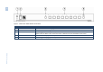
6 Figure 1: VS-81H 8x1 HDMI Switcher Front Panel # Feature Function 1 IR Receiver LED illuminates when receiving signals from the infrared remote control transmitter 2 POWER Switch Illuminated switch for turning the unit ON or OFF 3 OFF Button Press to toggle disconnecting the output Flashes when the EDID of the connected monitor is different from the last EDID that was saved 4 INPUT SELECTOR Buttons Press to select an input (from 1 to 8) 5 PANEL LOCK Button Press to toggle disengaging the
VS-81H – Overview Figure 2: VS-81H 8x1 HDMI Switcher Rear Panel # Feature Function 6 INPUT HDMI Connectors Connect to the HDMI sources (from 1 to 8) 7 RS-232 9-pin D-sub Connector Connects to a PC or an RS-232 remote controller 8 ETHERNET Connector Connects to a PC, Ethernet controller or network 9 RESET Button Press to reset to the factory default definitions: First disconnect the power cord and then connect it again while pressing the RESET button.
4 Installing in a Rack This section provides instructions for rack mounting the unit.
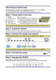
5 Connecting the VS-81H i Always switch off the power to each device before connecting it to your VS-81H. After connecting your VS-81H, connect its power and then switch on the power to each device. To connect the VS-81H 8x1 HDMI Switcher (as illustrated in Figure 3), do the following: 1. If required: Set the appropriate INPUTS to the DVD mode (see Section 6.1) Acquire the EDID (see Section 6.2) 2. Connect the HDMI sources as follows: You do not have to connect all the HDMI sources.
Figure 3: Connecting the VS-81H 8x1 HDMI Switcher 10 VS-81H - Connecting the VS-81H
6 Operating the VS-81H This section describes: 6.1 • The PC mode and the DVD mode (see Section 6.1) • How to acquire the EDID (see Section 6.2) • How to control the machine via RS-232 (see Section 6.3) • How to control the machine via the ETHERNET port (see Section 6.
3. Keep pressing and holding the PANEL LOCK button for a few seconds and then release it. The LOCK button flashes. If an input button illuminates, this indicates that that input is set to the DVD mode. If an input button is not illuminated, this indicates that that input is set to the PC mode. 4. Press an input to toggle between the PC mode (input button not illuminated) and the DVD mode (input button illuminated). 5. To exit this mode, press the PANEL LOCK button. 6.
3. Release the PANEL LOCK and INPUT 8 buttons. If an output was connected, the output EDID is read to all the inputs. If an output was not connected to the machine, the default EDID is read to the inputs. 6.3 Connecting via the RS-232 Port You can connect to the VS-81H to a PC or RS-232 controller using the RS-232 connection. Note that a null-modem adapter/connection is not required.
3. Right-click Local Area Connection Properties. 4. Select Properties. The Local Area Connection Properties window appears. 5. Select the Internet Protocol (TCP/IP) and click the Properties Button (see Figure 4). Figure 4: Local Area Connection Properties Window 6. Select Use the following IP Address, and fill in the details as shown in Figure 5. 7. Click OK.
Figure 5: Internet Protocol (TCP/IP) Properties Window 6.4.2 Connecting the ETHERNET Port via a Network Hub (StraightThrough Cable) You can connect the Ethernet port of the VS-81H to the Ethernet port on a network hub or network router, via a straight through cable with RJ-45 connectors. 6.4.3 Configuring Several Units via the Ethernet Port To control several units via the Ethernet, connect each unit via the Ethernet port to the LAN port of your PC.
7 Technical Specifications INPUTS: 8 HDMI connectors OUTPUT: 1 HDMI connector MAX. DATA RATE: Up to 6.75Gbps (2.
8 Default Communication Parameters RS-232 Protocol 2000 Baud Rate: 9600 Data Bits: 8 Stop Bits: 1 Parity: None Command Format: HEX Example (Output 1 to Input 1): 0x01, 0x81, 0x81, 0x81 Ethernet IP Address: 192.168.1.39 TCP Port Number: 5000 Network Mask: 255.255.255.0 Default Gateway: 192.168.1.
9 Protocol 2000 Kramer Protocol 2000 for RS-232/RS-485 communication uses four bytes of information as defined below. MSB 0 7 1st byte 1 7 2nd byte 1 7 3rd byte 1 7 4th byte LSB DESTINATION D 6 N5 5 INSTRUCTION N4 N3 4 3 N2 2 N1 1 N0 0 INPUT I6 6 I5 5 I4 4 I3 3 I2 2 I1 1 I0 0 OUTPUT O6 6 O5 5 O4 4 O3 3 O2 2 O1 1 O0 0 OVR 6 X 5 MACHINE NUMBER M4 M3 4 3 M2 2 M1 1 M0 0 1st BYTE: Bit 7 – Defined as 0.
Instruction Codes for Protocol 2000 Instruction Definition for Specific Instruction # Input Description 1 SWITCH VIDEO 1 SWITCH VIDEO LOCK FRONT PANEL 31 REQUEST WHETHER PANEL IS LOCKED 61 IDENTIFY MACHINE 30 Notes Output 2, 15 Set equal to video input which is to be switched (0 = disconnect) Set equal to video input which is to be switched (0 = disconnect) 0 - Panel unlocked 1 - Panel locked 0 Set equal to video output which is to be switched (0 = to all the outputs) Set equal to video output
20 VS-81H - Protocol 2000
! ! PN: 2900- 000670 " " Rev: 3