
user manual


VS-81H - Protocol 2000 19
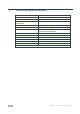
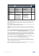
Instruction Codes for Protocol 2000
Instruction Definition for Specific Instruction Notes
# Description Input Output
1
SWITCH VIDEO
Set equal to video input which is
to be switched
(0 = disconnect)
Set equal to video output which is
to be switched
(0 = to all the outputs)
2, 15
1 SWITCH VIDEO
Set equal to video input which is
to be switched
(0 = disconnect)
Set equal to video output which is
to be switched
(0 = to all the outputs)
2, 15
30
LOCK FRONT
PANEL
0 - Panel unlocked
1 - Panel locked
0 2
31 REQUEST
WHETHER PANEL
IS LOCKED
0 0 16
61
IDENTIFY MACHINE
1 - video machine name
2 - audio machine name
3 - video software version
4 - audio software version
5 – RS-422 controller name
6 – RS-422 controller version
7 - remote control name
8 - remote software version
9 - Protocol 2000 revision
0 - Request first 4 digits
1 - Request first suffix
2 - Request second suffix
3 - Request third suffix
10 - Request first prefix
11 - Request second prefix
12 - Request third prefix
13
NOTES on the above table:
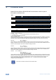
NOTE 2 – These are bi-directional definitions. That is, if the switcher receives the code, it will perform the instruction;
and if the instruction is performed (due to a keystroke operation on the front panel), then these codes are sent. For
example, if the HEX code
01 85 88 83
was sent from the PC, then the switcher (machine 3) will switch input 5 to output 8. If the user switched input 1 to output
7 via the front panel keypad, then the switcher will send HEX codes:
41 81 87 83
to the PC.
When the PC sends one of the commands in this group to the switcher, then, if the instruction is valid, the switcher
replies by sending to the PC the same four bytes that it was sent (except for the first byte, where the DESTINATION bit
is set high).
NOTE 13 – This is a request to identify the switcher/s in the system. If the OUTPUT is set as 0, and the INPUT is set as
1, 2, 5 or 7, the machine will send its name. The reply is the decimal value of the INPUT and OUTPUT. For example, for
a 2216, the reply to the request to send the audio machine name would be (HEX codes):
7D 96 90 81 (i.e. 128dec+ 22dec for 2nd byte, and 128dec+ 16dec for 3rd byte).
If the request for identification is sent with the INPUT set as 3 or 4, the appropriate machine will send its software
version number. Again, the reply would be the decimal value of the INPUT and OUTPUT - the INPUT representing the
number in front of the decimal point, and the OUTPUT representing the number after it. For example, for version 3.5, the
reply to the request to send the version number would be (HEX codes):
7D 83 85 81 (i.e. 128dec+ 3dec for 2nd byte, 128dec+ 5dec for 3rd byte).
If the OUTPUT is set as 1, then the ASCII coding of the lettering following the machine’s name is sent. For example, for
the VS-7588YC, the reply to the request to send the first suffix would be (HEX codes):
7D D9 C3 81 (i.e. 128dec+ ASCII for “Y”; 128dec+ ASCII for “C”).
NOTE 15 – When the OVR bit (4th byte) is set, then the “video” commands have universal meaning. For example,
instruction 1 (SWITCH VIDEO) will cause all units (including audio, data, etc.) to switch. Similarly, if a machine is in
“FOLLOW” mode, it will perform any “video” instruction.
NOTE 16 - The reply to the “REQUEST WHETHER PANEL IS LOCKED” is as in NOTE 4 above, except that here the
OUTPUT is assigned with the value 0 if the panel is unlocked, or 1 if it is locked.