KR AMER ELECTRON ICS LT D.
Contents 1 Introduction 1 2 2.1 Getting Started Achieving the Best Performance 2 2 3 Installing in a Rack 3 4 4.1 4.2 4.3 Your VM-1010 Overview Connecting the VM-1010 VM-1010 Technical Specifications 4 4 7 8 5 5.1 5.2 5.3 Your VM-1021 Overview Connecting the VM-1021 VM-1021 Technical Specifications 9 9 12 13 6 6.1 6.2 6.3 Your VM-1055 Overview Connecting the VM-1055 VM-1055 Technical Specifications 14 14 17 18 7 7.1 7.2 7.
1 Introduction Welcome to Kramer Electronics! Since 1981, Kramer Electronics has been providing a world of unique, creative, and affordable solutions to the vast range of problems that confront the video, audio, presentation, and broadcasting professional on a daily basis.
2 Getting Started We recommend that you: • Unpack the equipment carefully and save the original box and packaging materials for possible future shipment • Review the contents of this user manual • Use Kramer high-performance, high-resolution cables • Use only the power cord that is supplied with this machine Go to http://www.kramerelectronics.com to check for up-to-date user manuals, application programs, and to check if firmware upgrades are available (where appropriate). i 2.
3 Installing in a Rack This section provides instructions for rack mounting the 1U devices. 2U and 3U devices use the same procedure with longer rack “ears” and additional screws.
4 Your VM-1010 This section describes the VM-1010 Programmable Video Distributor. 4.1 Overview The VM−1010 is a high−performance distribution amplifier for composite video. It can also be configured as a 1:5 distribution amplifier for s−Video (Y/C) signals and has controls to compensate for signal losses inherent in long cable runs. The VM−1010 is designed for studio and other demanding applications. It has two looping video inputs, each splitting to 5 outputs.
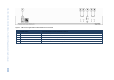
VM-1010, VM-1021, VN-1055, VM-54 – The VM-1010 Programmable Video Distributor Figure 1: VM-1010 Programmable Video Distributor Front Panel # Feature Function 1 POWER Switch Illuminated switch for turning the device on and off 2 CHANNEL B EQ Trimmer Controls cable equalization of channel B outputs 3 CHANNEL B LEVEL Trimmer Controls the video level of channel B outputs 4 MODE Button Selects either 1:10 or 2 x 1:5 operation 5 CHANNEL A EQ Trimmer Controls cable equalization of channel A outpu
6 8 9 10 11 12 13 14 15 16 17 6 CHANNEL A # 7 CHANNEL B VM-1010, VM-1021, VN-1055, VM-54 – The VM-1010 Programmable Video Distributor Figure 2: VM-1010 Programmable Video Distributor Rear Panel Feature OUT BNC Connectors (1A-5A) 5 amplified and buffered video outputs Function INPUT A BNC Connector Connects to a composite/component/YC/analog sync video source A 75Ω Button Selects "75Ω" or "HI-z" impedance (for looping select "Hi-z") DC Button Selects DC coupling when pushed LOOP BNC Connector
4.2 Connecting the VM-1010 i Always switch off the power to each device before connecting it to your VM-1010. After connecting your VM-1010, connect its power and then switch on the power to each device. To connect the VM-1010 as illustrated in the example in Figure 3: 1. Connect up to two video sources (for example composite video players) to CHANNEL A INPUT A and CHANNEL B INPUT B BNC connectors. 2. Connect up to five video acceptors (for example, composite video recorders) to each channel. 3.
Note: • Terminate unused inputs to 75Ω, and terminate active inputs at the connecting source • Remember, the output signal format matches the input signal format (for example, if the input is composite, the output is composite) • All signal cables to each device should be of equal length (for example, the R,G,B cables between a camera and the amplifier should be of equal length) 4.
5 Your VM-1021 This section describes the VM-1021 1:20 Video Distributor. 5.1 Overview The VM-1021 is a high-performance distribution amplifier for composite or SDI video signals. It provides controls to compensate for signal losses inherent in long cable runs. The VM-1021 is a full broadcast, state-of-the-art, 1:20 video distribution amplifier designed for studio and other demanding applications. The unit splits a single input source into twenty identical outputs with no discernible signal degradation.
10 VM-1010, VM-1021, VN-1055, VM-54 – The VM-1021 1:20 Video Distributor 10 Figure 4: VM-1021 1:20 Video Distributor Front Panel # Feature Function 1 POWER Switch Illuminated switch for turning the device on and off 2 SET 4 ADJUST EQ Trimmer Controls cable equalization of SET 4 video outputs 16-20 3 SET 4 ADJUST LEVEL Trimmer Controls level of SET 4 video outputs 16-20 4 SET 3 ADJUST EQ Trimmer Controls cable equalization of SET 3 video outputs 11-15 5 SET 3 ADJUST LEVEL Trimmer Controls
VM-1010, VM-1021, VN-1055, VM-54 – The VM-1021 1:20 Video Distributor Figure 5: VM-1021 1:20 Video Distributor Rear Panel 14 # Feature INPUT BNC Connector Function Connects to a composite/component/ analog sync video source 15 LOOP BNC Connector Selects “75Ω“ or “HI-z” impedance when pressed (for looping select "Hi-z") 16 IN=75Ω Button Provides video looping capability to increase number of outputs 17 OUT SET 1 BNC Connectors (1-5) SET 1 of 5 amplified buffered and clamped video outputs 1-5 18
5.2 Connecting the VM-1021 i Always switch off the power to each device before connecting it to your VM-1021. After connecting your VM-1021, connect its power and then switch on the power to each device. To connect the VM-1021 as illustrated in the example in Figure 6: 1. Connect a video source to the INPUT BNC connector (for example, a composite video player). 2. Connect the OUT SET BNC connectors to up to 20 video acceptors, 4 sets of 5 devices (for example, composite video recorders or displays). 3.
Note: • Terminate unused inputs to 75Ω, and terminate active inputs at the connecting source • Remember, the output signal format matches the input signal format (for example, if the input is composite, the output is composite) • All signal cables to each device should be of equal length (for example, the R,G,B cables between a camera and the amplifier should be of equal length) 5.
6 Your VM-1055 This section describes the VM-1055 Video Component Distributor. 6.1 Overview The VM-1055 is a high-performance distribution amplifier for RGBHV video signals. It provides correct buffering and isolation and distributes the signal to five identical outputs. The VM-1055 is a full broadcast, component video /RGBHV distributor designed for studios, graphics workstations, presentation and other demanding applications.
VM-1010, VM-1021, VN-1055, VM-54 – The VM-1055 Video Component Distributor Figure 7: VM-1055 Video Component Distributor Front Panel # 1 Feature Function POWER Switch Illuminated switch for turning the device on and off 15 VM-1010, VM-1021, VN-1055, VM-54 - Your VM-1055 15
16 VM-1010, VM-1021, VN-1055, VM-54 – The VM-1055 Video Component Distributor Figure 8: VM-1055 Video Component Distributor Rear Panel # 16 2 75Ω Switch Feature Function Selects “75Ω“or “HI-z” impedance for Hs channel. When at the "75Ω" position, the signal applied to the connector should be analog video or sync signal.
6.2 Connecting the VM-1055 i Always switch off the power to each device before connecting it to your VM-1055. After connecting your VM-1055, connect its power and then switch on the power to each device. To connect the VM-1055 as illustrated in the example in Figure 9: 1. Connect up to 5 video sources (for example, the RGBHV output from a PC video card) to the IN BNC connectors. 2. Connect the OUT BNC connectors to up to 5 video acceptors (for example, the RGBHV projectors and displays). 3.
Note: • Terminate unused inputs to 75Ω, and terminate active inputs at the connecting source • Remember, the output signal format matches the input signal format (for example, if the input is composite, the output is composite) • All signal cables to each device should be of equal length (for example, the R,G,B cables between a camera and the amplifier should be of equal length) 6.
7 Your VM-54 This section describes the VM-54 Video/Component Distributor Amplifier. 7.1 Overview The VM-54 is a high-quality video/component distribution amplifier designed for studio and other demanding applications. The unit has three looping input channels each with 18 outputs. With this configuration a 1:18 RGB distributor can be formed. Each channel is subdivided into four groups of five or three outputs, which may be tuned separately for gain and cable EQ.
20 VM-1010, VM-1021, VN-1055, VM-54 – The VM-54 Video/Component Distributor Amplifier Figure 10: VM-54 Video/Component Distributor Amplifier Front Panel # 20 Feature Function 1 POWER Switch Illuminated switch for turning the device on and off 2 EQ and GAIN Trimmers for OUTPUTS 16-18 (Channels 1-3) Controls cable equalization and gain levels of video outputs 16-18 in channels 1-3 3 EQ and GAIN Trimmers for OUTPUTS 11-15 (Channels 1-3) Controls cable equalization and gain levels of video outputs
VM-1010, VM-1021, VN-1055, VM-54 – The VM-54 Video/Component Distributor Amplifier Figure 11: VM-54 Video/Component Distributor Amplifier Rear Panel 8 # Feature INPUT BNC Connectors (Channels 1-3) Video input (channels 1-3) Function 9 LOOP BNC Connectors (Channels 1-3) Provides video looping capability to increase number of outputs (channels 1-3) 10 OUTPUTS 1-5 (Channels 1-3) 11 OUTPUTS 6-10 (Channels 1-3) 12 OUTPUTS 11-15 (Channels 1-3) 13 OUTPUTS 16-18 (Channels 1-3) 14 Power Connector
7.2 Connecting the VM-54 i Always switch off the power to each device before connecting it to your VM-54. After connecting your VM-54, connect its power and then switch on the power to each device. To connect the VM-54 as illustrated in the example in Figure 12: 1. Connect an RGB video source (for example, an RGM camera) to the BNC connectors of the 3 INPUT channels. 2. Connect the 3 channels of the OUTPUT BNC connectors to up to 18 video acceptors (for example, RGB displays). 3.
Note: • Terminate unused inputs to 75Ω, and terminate active inputs at the connecting source • Remember, the output signal format matches the input signal format (for example, if the input is composite, the output is composite) • All signal cables to each device should be of equal length (for example, the R,G,B cables between a camera and the amplifier should be of equal length) 7.
! ! P/N: 2900- 300182 " " Rev: 1