Kramer Electronics, Ltd.
Contents Contents 1 2 3 4 5 6 Introduction Getting Started Overview Your VP-100A XGA / Audio Interface Connecting the VP-100A Technical Specifications 1 1 2 2 5 6 Figures Figure 1: VP-100A XGA / Audio Interface Figure 2: VP-100A Underside Figure 3: Connecting the Balanced Stereo Audio Output to a Balanced Acceptor Figure 4: Connecting the Balanced Stereo Audio Output to an Unbalanced Acceptor Figure 5: VP-100A XGA / Audio Interface 3 4 5 5 6 Tables Table 1: Front Panel VP-100A XGA / Audio Interface Fe
Introduction 1 Introduction Welcome to Kramer Electronics (since 1981): a world of unique, creative and affordable solutions to the infinite range of problems that confront the video, audio and presentation professional on a daily basis. In recent years, we have redesigned and upgraded most of our line, making the best even better! Our 350-plus different models now appear in 8 Groups1, which are clearly defined by function. Congratulations on purchasing your Kramer VP-100A XGA / Audio Interface.
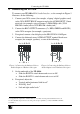
Overview 3 Overview The VP-100A is a high performance XGA and audio interface that accepts a computer graphics (XGA) signal on an HD15 connector and outputs it to RGBHV1 on BNC connectors, and also converts an unbalanced stereo audio signal to balanced stereo audio. In addition, the VP-100A includes: A video bandwidth of 430MHz, to ensure transparent operation at multiple resolutions including UXGA A local monitor loop-through on an active HD15F connector An unbalanced stereo audio input on a 3.
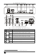
Your VP-100A XGA / Audio Interface Figure 1: VP-100A XGA / Audio Interface Table 1: Front Panel VP-100A XGA / Audio Interface Features 4 5 6 7 8 V SHIFT H SHIFT 3 Feature POWER Switch Trimmer ON/OFF Switch Trimmer ON/OFF Switch XGA EQ.
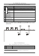
Your VP-100A XGA / Audio Interface Table 2: Rear Panel VP-100A XGA / Audio Interface Features Feature Hs BNC Connector Vs BNC Connector Cs BNC Connector RED BNC Connector GREEN BNC Connector BLUE BNC Connector XGA INPUT HD15 Connector XGA LOOP HD15 Connector AUDIO INPUT 3.
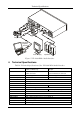
Connecting the VP-100A 5 Connecting the VP-100A To connect your VP-100A XGA / Audio Interface, as the example in Figure 5 illustrates, do the following: 1. Connect your XGA source (for example, a laptop’s digital graphics card) to the XGA INPUT HD15F connector and to the AUDIO INPUT 3.5mm mini jack, for example, using a Kramer C-GMA/GMA cable (VGA HD15M +Audio jack to VGA HD15M +Audio jack)1. 2. Connect the BNC OUTPUT connectors (Cs, RED, GREEN and BLUE2) to the XGA acceptor (for example, a projector). 3.
Technical Specifications Projector Computer Graphics Source Local Display Speakers Figure 5: VP-100A XGA / Audio Interface 6 Technical Specifications Table 4: Technical Specifications of the VP-100A XGA / Audio Interface INPUTS: VIDEO: 1 XGA on HD15F connector; 1 XGA on HD15F loop OUTPUTS: VIDEO: R, G, B, Hs, Vs, Cs on BNC double connectors MAX. OUTPUT LEVEL: VIDEO: 2Vpp BANDWIDTH (-3dB): VIDEO: 430MHz DIFF. GAIN: 1.3% DIFF. PHASE: 0.35 Deg. K-FACTOR: <0.05% S/N RATIO: VIDEO: 79dB CONTROLS: 0 to +5.
LIMITED WARRANTY Kramer Electronics (hereafter Kramer) warrants this product free from defects in material and workmanship under the following terms. HOW LONG IS THE WARRANTY Labor and parts are warranted for seven years from the date of the first customer purchase. WHO IS PROTECTED? Only the first purchase customer may enforce this warranty. WHAT IS COVERED AND WHAT IS NOT COVERED Except as below, this warranty covers all defects in material or workmanship in this product.
For the latest information on our products and a list of Kramer distributors, visit our Web site: www.kramerelectronics.com, where updates to this user manual may be found. We welcome your questions, comments and feedback. Safety Warning: Disconnect the unit from the power supply before opening/servicing. Caution Kramer Electronics, Ltd. Web site: www.kramerelectronics.com E-mail: info@kramerel.