
User Guide

Connecting the VP-100A
5
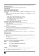
5 Connecting the VP-100A
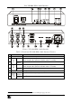
To connect your VP-100A XGA / Audio Interface, as the example in Figure 5
illustrates, do the following:
1. Connect your XGA source (for example, a laptop’s digital graphics card)
to the XGA INPUT HD15F connector and to the AUDIO INPUT 3.5mm
mini jack, for example, using a Kramer C-GMA/GMA cable (VGA
HD15M +Audio jack to VGA HD15M +Audio jack)
1
.
2. Connect the BNC OUTPUT connectors (Cs, RED, GREEN and BLUE
2
)
to the XGA acceptor (for example, a projector).
3. If required, connect a local display to the HD15F XGA LOOP port.
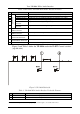
4. Connect the balanced stereo AUDIO OUTPUT terminal block to an
acceptor (for example, speakers), as one of the following:
L+ L- G R+ R-
+ - G + -
Figure 3: Connecting the Balanced Stereo
Audio Output to a Balanced Acceptor
L+ L- G R+ R-
+ - G + -
Figure 4: Connecting the Balanced Stereo
Audio Output to an Unbalanced Acceptor
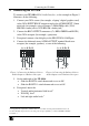
5. On the underside of the VP-100A:
Slide the ID BIT 4 switch downwards to set to ON
Slide the ID BIT 11 switch downwards to set to ON
6. If required, adjust the:
Vertical and/or horizontal shift levels
3
XGA EQ. level
3
Left and right audio levels
3
1 Not supplied. The complete list of Kramer cables is on our Web site at http://www.kramerelectronics.com
2 Connect the BNC output connectors according to the acceptor capabilities: you may use RGBHV or RGBCs
3 See Table 1