
Owner's manual


KRAMER: SIMPLE CREATIVE TECHNOLOGY
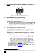
Defining the VP-16x18AK 16 x 18 PC UXGA/Audio Router
8
Table 1: VP-16x18AK 16 x 18 PC UXGA/Audio Router Front Panel Features
# Feature Function
1 SELECTOR IN Buttons Press to select an input (from 1 to 16) following the selection of an output (see Section 7.2).
When an input signal is detected, the corresponding input button lights
2 SELECTOR OUT
Buttons
Press to select an output (from 1 to 18) followed by an input selection (see Section 7.2)
3 OFF Button Press a SELECTOR OUT button followed by OFF to disconnect the selected output from the input (see Section 7.2).
Press ALL followed by OFF to disconnect all outputs
4 ALL Button Press ALL followed by an INPUT button to switch the selected input to all outputs
1
Section (see 7.2)
5 STATUS LCD Readout Displays the current Input-Output switching configuration
2
6
on a 2 line LCD readout
IR Sensor IR receiver for the Remote Control IR transmitter
7 IR LED Lights yellow when a signal is received from the IR transmitter
8 POWER LED Lights green when the unit receives power and is switched on
9 VIDEO Button Press for subsequent actions to relate to video. The button lights when the video mode is active.
Press in conjunction with AUDIO to set the delay time
10 AUDIO Button Press for subsequent actions to relate to audio. The button lights when the audio mode is active.
Press in conjunction with VIDEO to set the delay time
11 TAKE Button Press to set the Confirm mode
3
Section
(where user confirmation is required for switching actions); press again to set the At Once mode (where
user confirmation per action is not required). When in Confirm mode, press the TAKE button to execute pending actions (see 7.3.2)
12 AFV Button Press to make the audio channels follow the video channel switching. The button lights when the AFV mode is active (see Section 7.6)
13 RCL (Recall) Button Press in conjunction with an Output button to recall a switching preset (see Section 7.7.2). Press again to execute the preset.
Press in conjunction with STO to set the machine number
14 STO (Store) Button Press followed by an Output button to store the current switching configuration (see Section 7.7.1).
Press in conjunction with RCL to set the machine number
15 AUDIO GAIN Button Press (following selection of an output or input) to set the audio input or output gain (see Section 7.4)
16
AUDIO
LEVEL
– Button Press (following the Audio Gain button) to decrease the audio signal level (input, output, bass or treble)
17 + Button Press (following the Audio Gain button) to increase the audio input signal level (input, output, bass or treble)
18 LOCK Button Press and hold to lock the front panel buttons, press and hold again to unlock the buttons. The button lights when the front panel is locked
(see Section
9.2.5)
1 For example, press ALL and then IN button 2 to connect input 2 to all the outputs
2 Also displays the number of input and output ports, the firmware version number and the machine number (see Section
6.6)
3 When in the Confirm mode, the TAKE button lights