
Owner's manual


KRAMER: SIMPLE CREATIVE TECHNOLOGY
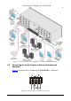
Defining the VP-16x18AK 16 x 18 PC UXGA/Audio Router
10
Table 2: VP-16x18AK 16 x 18 PC UXGA/Audio Router Rear Panel Features
# Feature Function
1 VIDEO INPUTS 15-pin HD (F) Connectors Connect to the VGA
1
2
sources (from 1 to 16)
AUDIO OUTPUTS Removable Terminal Block
Connectors
Connect to balanced stereo audio acceptors (from 1 to 16)
3
VIDEO OUTPUTS
VGA 15-pin HD (F)
Connectors
Connect to the VGA
1
acceptors (from 1 to 16)
4 OUTPUT 17, OUTPUT 18
RJ-45 TP Connectors
Connect to compatible TP receivers (for example, TP-122N/TP-142)
5 REMOTE IR Opening
2
Mount the optional internal IR connection cable that connects to an external IR receiver unit for
controlling the machine via an IR remote controller instead of using the front panel IR receiver
6 AUDIO INPUTS 3.5mm Mini Jacks Connect to the unbalanced stereo audio sources (from 1 to 16)
7 RESET Button Press and hold while powering up the unit to reset all audio, switching and Ethernet settings to
their factory default values (see Section
12)
8 PROG Button For the use of Kramer service personnel only
9 RS-485 3-pin Terminal Block Connect to the corresponding pins A(+), B(–) and G on another device for RS-485
communication (see Section
6.4)
10 RS-232 9-pin D-sub Serial Port Connect to a PC or remote controller (see Section 6.3)
11 ETHERNET RJ-45 Connector Connect to a PC or other controller over a LAN (see Section 6.5)
12 MACH # DIP-switches (1, 2 and 3) Use to set the RS-485 machine number (see Section 6.6)
13 RS-485 TERM DIP-switch (4)
Use to set the RS-485 termination
3
Section
: ON (down) for RS-485 line termination with 120Ω;
OFF (up) for no RS-485 line termination (see 6.6)
14 Mains Power Connector Connect to the AC mains power supply
15 Fuse Holder Mains fuse holder
16 Power Switch Switch for turning the unit on and off
1 Up to UXGA resolution
2 Covered by a removable cap. The 3.5mm mini jack at the end of the internal IR connection cable fits into this opening
3 Terminate the first and the last physical units on the RS-485 bus (on). Leave all other units unterminated (off)