Kramer Electronics, Ltd.
Contents Contents 1 2 2.1 3 4 5 5.1 5.2 5.3 6 6.1 Introduction Getting Started Quick Start Overview Your VP-2x2 2x2 XGA/Audio Matrix Switcher Connecting the VP-2x2 2x2 XGA/Audio Matrix Switcher Connecting the VP-2x2 2x2 XGA/Audio Matrix Switcher Rear Panel Connecting the Balanced/Unbalanced Stereo Audio Input/Output Connecting a PC Operating Your XGA/Audio Matrix Switcher Choosing the Audio-Follow-Video or Breakaway Option 1 1 1 3 4 5 5 7 8 9 9 6.1.1 6.1.
Introduction 1 Introduction Welcome to Kramer Electronics! Since 1981, Kramer Electronics has been providing a world of unique, creative, and affordable solutions to the vast range of problems that confront the video, audio, presentation, and broadcasting professional on a daily basis. In recent years, we have redesigned and upgraded most of our line, making the best even better! Our 500-plus different models now appear in eight groups1 that are clearly defined by function.
Getting Started 2 KRAMER: SIMPLE CREATIVE TECHNOLOGY
Overview 3 Overview The VP-2x2 is a high performance matrix switcher for VGA/SVGA/XGA/UXGA signals and balanced stereo audio signals. The user can simultaneously route an input to one or both outputs1.
Your VP-2x2 2x2 XGA/Audio Matrix Switcher 4 Your VP-2x2 2x2 XGA/Audio Matrix Switcher Figure 1 and Table 1 define the front and rear panels of the VP-2x2: Figure 1: VP-2x2 2x2 XGA/Audio Matrix Switcher Table 1: VP-2x2 2x2 XGA/Audio Matrix Switcher Features # Feature 1 2 3 4 5 6 7 8 POWER Switch 9 10 11 12 13 14 15 16 17 18 Function Illuminated switch for turning the unit ON or OFF IN 1 To OUT 2 Switches input 1 to output 2 IN 1 To OUT 1 Switches input 1 to output 1 1 SELECT Buttons IN 2 To OUT 1 S
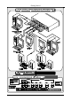
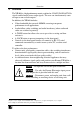
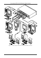
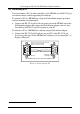
Connecting the VP-2x2 2x2 XGA/Audio Matrix Switcher 5 Connecting the VP-2x2 2x2 XGA/Audio Matrix Switcher This section describes how to connect: The VP-2x2 rear panel (see section 5.1) A balanced stereo audio input/output (see section 5.2) The VP-2x2 to a controlling device via RS-232 (see section 5.2) 5.1 Connecting the VP-2x2 2x2 XGA/Audio Matrix Switcher Rear Panel To connect1 the VP-2x2, as illustrated in the example in Figure 2, do the following2: 1.
Connecting the VP-2x2 2x2 XGA/Audio Matrix Switcher Figure 2: Connecting the VP-2x2 2x2 XGA/Audio Matrix Switcher 6 KRAMER: SIMPLE CREATIVE TECHNOLOGY
Connecting the VP-2x2 2x2 XGA/Audio Matrix Switcher 5.
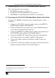
Connecting the VP-2x2 2x2 XGA/Audio Matrix Switcher 5.3 Connecting a PC You can connect a PC (or other controller) to the VP-2x2 via the RS-232 port for remote control, and for upgrading the firmware.
Operating Your XGA/Audio Matrix Switcher 6 Operating Your XGA/Audio Matrix Switcher Operate your VP-2x2 via: The front panel buttons RS-232 serial commands transmitted by a touch screen system, PC, or other serial controller 6.
Technical Specifications 6.2 Locking the Front Panel To prevent changing the settings accidentally or tampering with the unit via the front panel buttons, lock1 your VP-2x2. Unlocking releases the protection mechanism. To lock the VP-2x2: Press the LOCK button for more than two seconds, until the LOCK button is illuminated The front panel is locked.
Kramer Protocol 2000 8 Kramer Protocol 20001 The VP-2x2 is compatible with Kramer’s Protocol 2000 (version 0.50) (below). This RS-232/RS-485 communication protocol uses four bytes of information as defined below. For RS-232, a null-modem connection between the machine and controller is used. The default data rate is 9600 baud, with no parity, 8 data bits and 1 stop bit.
Kramer Protocol 2000 For a single machine controlled via the serial port, always set M4…M0 = 1, and make sure that the machine itself is configured as MACHINE NUMBER = 1. Table 4: Instruction Codes for Protocol 2000 Note: All values in the table are decimal, unless otherwise stated.
Table of Hex Codes for Serial Communication NOTE 6 – If INPUT is set to 127 for these instructions, then, if the function is defined on this machine, it replies with OUTPUT=1. If the function is not defined, then the machine replies with OUTPUT=0, or with an error (invalid instruction code). If the INPUT is set to 126 for these instructions, then, if possible, the machine will return the current setting of this function, even for the case that the function is not defined.
LIMITED WARRANTY Kramer Electronics (hereafter Kramer) warrants this product free from defects in material and workmanship under the following terms. HOW LONG IS THE WARRANTY Labor and parts are warranted for seven years from the date of the first customer purchase. WHO IS PROTECTED? Only the first purchase customer may enforce this warranty. WHAT IS COVERED AND WHAT IS NOT COVERED Except as below, this warranty covers all defects in material or workmanship in this product.
For the latest information on our products and a list of Kramer distributors, visit our Web site: www.kramerelectronics.com, where updates to this user manual may be found. We welcome your questions, comments and feedback. Safety Warning: Disconnect the unit from the power supply before opening/servicing. Caution Kramer Electronics, Ltd. Web site: www.kramerelectronics.com E-mail: info@kramerel.