K R A ME R E LE CT R O N IC S L TD .
Contents 1 Introduction 1 2 2.1 2.2 2.3 3 3.1 3.2 3.3 3.4 Getting Started Achieving the Best Performance Safety Instructions Recycling Kramer Products Overview HDCP Compliance About HDBaseT™ Technology Using Twisted Pair Cable Defining the VP-774AMP Presentation Switcher/Scaler 2 2 2 3 4 7 7 7 7 4 Installing in a Rack 11 5 5.1 5.2 5.3 5.4 6 6.1 6.2 6.3 6.4 6.5 6.6 6.7 6.
Figures Figure 1: VP-774AMP Presentation Switcher/Scaler Front Panel Figure 2: VP-774AMP Presentation Switcher/Scaler Rear Panel Figure 3: 15-pin HD Connector Pinout Figure 4: Connecting the VP-774AMP Presentation Switcher/Scaler Figure 5: TP PINOUT Figure 6: Connecting the Balanced Stereo Audio Output Figure 7: Connecting an Unbalanced Stereo Audio Acceptor to the Balanced Output Figure 8: Microphone Pinout Figure 9: Audio Input Pinout Figure 10: Input Menu Figure 11: Select the Display Mode Figure 12: Cha
1 Introduction Welcome to Kramer Electronics! Since 1981, Kramer Electronics has been providing a world of unique, creative, and affordable solutions to the vast range of problems that confront video, audio, presentation, and broadcasting professionals on a daily basis.
2 Getting Started We recommend that you: Unpack the equipment carefully and save the original box and packaging materials for possible future shipment Review the contents of this user manual i 2.1 Go to http://www.kramerelectronics.com/support/product_downloads.asp to check for up-to-date user manuals, application programs, and to check if firmware upgrades are available (where appropriate).
2.3 Recycling Kramer Products The Waste Electrical and Electronic Equipment (WEEE) Directive 2002/96/EC aims to reduce the amount of WEEE sent for disposal to landfill or incineration by requiring it to be collected and recycled. To comply with the WEEE Directive, Kramer Electronics has made arrangements with the European Advanced Recycling Network (EARN) and will cover any costs of treatment, recycling and recovery of waste Kramer Electronics branded equipment on arrival at the EARN facility.
3 Overview The Kramer VP-774AMP is a high quality presentation switcher and scaler. It accepts one of nine inputs: an SDI signal on a BNC connector, a DisplayPort (DP) signal on a DisplayPort connector, one composite video signal on an RCA connector, two computer graphics signals on 15-pin HD connectors, and four HDMI signals on HDMI connectors.
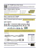
Scaled Outputs – 2 HDMI outputs, an SDI output and an HDBaseT TP output simultaneously HDBaseT™ technology with a bandwidth of up to 6.75Gbps (2.25Gbps per graphic channel) Up to 130m (430ft) normal mode; up to 180m (590ft) Ultra mode (1080p @60Hz @24bpp) when using BC-DGKat623 cables i For optimum range and performance, use Kramer's BC−DGKat524, BC−DGKat623 and BC−DGKat7a23 shielded twisted pair (STP) cables.
embedded audio inputs or performs an analog takeover to output the respective analog audio input Selectable Power Save modes for energy efficient usage HDCP Compliant - The HDCP (High Definition Content Protection) license agreement allows copy-protected data on the HDMI input to pass only to the HDMI output In addition, the VP-774AMP Presentation Switcher / Scaler: Includes luma keying via the PiP window Features advanced EDID management (native resolution and color depth) per input Anal
Remotely, from the infrared remote control transmitter Via the Ethernet (optionally via the Web pages) The VP-774AMP is housed in a 19” 1U rack mountable enclosure, with rack “ears” included, and is fed from a 100-240 VAC universal switching power supply. 3.1 HDCP Compliance i If an HDMI signal is HDCP protected, it can only appear on HDMI and HDBaseT outputs that are connected to HDCP compliant displays.
8 Figure 1: VP-774AMP Presentation Switcher/Scaler Front Panel # Feature 1 IR Receiver 2 IR LED 3 INPUT Selector Buttons Function Accepts IR remote commands Lights red when the unit accepts IR remote commands HDMI Press to select the HDMI input (from 1 to 4) PC Press to select the computer graphics input (from 1 to 2) 5 CV Press to select the composite video input (from 1 to 2) 6 DP Press to select the Display Port input 7 SDI 4 Press to select the SDI input 8 PIP Button Toggles the
VP-774 – Overview Figure 2: VP-774AMP Presentation Switcher/Scaler Rear Panel # Feature Connect to an unbalanced audio source for audio takeover of the HDMI 1 to HDMI 4 embedded audio (see Section 6.3). The pinout is defined in Section 5.4 PC 3.5mm Mini Jack Connect to the unbalanced stereo audio of the computer graphics source (from 1 to 2). The pinout is defined in Section 5.4 20 DP 3.
10 # Feature Function 33 CV IN RCA Connect to the composite video source 34 DP IN Connect to the DisplayPort source 35 SDI IN BNC Connect to the SDI source 36 SDI LOOP BNC Connect to a local display 37 SDI OUT BNC Connect to an SDI acceptor HDMI OUT Connect to an HDMI acceptor (from 1 to 2) HDBT OUT RJ-45 Connect to an HDBT receiver (for example, Kramer TP-580Rxr) to pass audio and video signals as well as serial commands LINK LED Lights to indicate a link 38 39 40 VIDEO OUTPUT Con
4 Installing in a Rack This section provides instructions for rack mounting the unit.
5 Connecting the VP-774AMP ! Always switch off the power to each device before connecting it to your VP-774AMP. After connecting your VP-774AMP, connect its power and then switch on the power to each device. i You do not have to connect all the inputs and outputs, connect only those that are required. To connect the VP-774AMP, as illustrated in the example in Figure 4, do the following: 1. Connect an HDMI source (for example, a DVD player) to the HDMI 1 IN VIDEO INPUT connector.
6. Connect an SDI source (for example, an SDI digital camera) to the SDI IN BNC connector. 7. Connect the SDI LOOP BNC connector to an SDI monitor (for example, an SDI display). 8. Connect the SDI OUT BNC connector to an SDI acceptor (for example, an SDI display with speakers). 9. Connect the HDMI 1 OUT connector to an HDMI acceptor (for example, a plasma display). You can also connect the HDMI OUT 2 output (not shown in Figure 4) 10.
Figure 4: Connecting the VP-774AMP Presentation Switcher/Scaler 14 VP-774AMP - Connecting the VP-774AMP
5.1 Wiring the RJ-45 Connectors This section defines the TP pinout, using a straight pin-to-pin cable with RJ-45 connectors.
5.2 Connecting the Balanced Stereo Audio Output Figure 6: Connecting the Balanced Stereo Audio Output 5.3 Figure 7: Connecting an Unbalanced Stereo Audio Acceptor to the Balanced Output Microphone Pinout This section defines the microphone 6mm jack pinout. Figure 8: Microphone Pinout 5.4 Audio Input Pinout This section defines the audio input 3.5mm jack pinout.
6 The OSD Menu The VP-774AMP OSD menu lets you set the operation parameters for the: Main Window Control PIP Window Control Entire System Control The nature of the operation setup appears in the OSD title, as shown in the example in Section 6.
The subtitle, below the title line shows the current level accessed (Scale in this example) After selecting Output (which is the second Level), it appears in the subtitle Once Master Connection is selected, the Title changes to “Entire System Control” indicating that the selection will affect the entire system.
Note that: A selected parameter that turns gray becomes valid immediately. You can press Enter at this point to save these parameter changes to the memory immediately (the screen will display “Saving Data” for a split second). In any case, exiting the menu saves the parameter to the memory Data is saved per window and per input (to a dedicated input + window memory), as applicable The control buttons let you control the VP-774AMP via the OSD menu.
6.2 The Input Menu Figure 10: Input Menu Setting Function Display Mode Select the display mode (see Figure 11): Single Window – single window mode operation with one channel displayed E Picture in Picture (PiP) – dual window mode operation, a smaller window superimposed over a full screen image (see Section 7.2) E Picture + Picture (PoP) – dual window mode operation, both images appear side-by-side and the aspect ratios of both images are maintained (see Section 7.
Setting Function Input Settings Set the: H Image Shift – to set the horizontal position of the image within the window M/P Volatile parameter V Image Shift – to set the vertical position of the image within the window M/P Volatile parameter Auto Positioning – to search the input image during the tuning process and automatically position it on the output window in a perfect fit.
The display mode setup, shown in Figure 11, is part of the entire system control and the selected Single Window also shows the current aspect ratio (Best Fit): Figure 11: Select the Display Mode 6.2.1 Window Customization Window customization lets you change the size and position of a selected window. Make sure that you have control over the window that requires customization (Main Window Control or PiP Window Control). If not, select it via the OSD item in the Miscellaneous menu, see Section 6.8.
Figure 12: Changing the Size of the Window To change the size of the window, do the following: 1. Check that window control is set as required (for example, PiP Window Control). 2. Select Window Customization (see Figure 16). 3. Select H width (an OSD slide bar appears) and press + to increase the width, or – to decrease the width, see Figure 13. The following example shows how to increase the width of the window Figure 13: Increasing the Width 4.
Figure 14: Increasing the Height 6.2.1.2 Moving the Position of the Main and/or PiP Window Use the H Position and V Position items in the OSD to change the position of the window using the + and – buttons on the front panel or remote control transmitter (as illustrated in Figure 15). Figure 15: Positioning the Window To move the position of the window, do the following: 1. Check that window control is set as required (for example, PiP Window Control).
2. Select Window Customization. The following Window appears: Figure 16: Window Customization 3. To move the picture to the right, select H Position. An OSD slide bar appears: Figure 17: H-Position Slide Bar 4. Press the +/- buttons to move the PiP window horizontally. Use the V Position menu item in the same way to move the PiP vertically, see Figure 18.
Figure 18: Moving the PiP Window i 26 Note that the sequence in which you change the size and position of the window is insignificant, as long as you make sure that the resized image does not go beyond the window boundaries.
6.3 The Audio Menu Figure 19: Audio Menu Setting Volume Function Set the input/output volume level [dB], see Figure 20 E. Set the: Input Volume [dB] – to adjust the audio input level Output Volume [dB] – to adjust the audio output level The output audio level can also be set via the + and – buttons on the front panel buttons (when not in the OSD mode) and/or the IR remote control transmitter buttons (see Section 8.
Setting Function Mic Effects (continued) For Mic 2, set the: Mic2 Mix [dB] – set to 1 to enable the Talkover mode or set to any other value to decrease the Mic2 volume without changing the Line out and Mic1 volume levels.
Figure 20: Set the Output Volume Level 6.3.1 SDI Channeling SDI channeling includes four groups with two stereo channels each. Two of the groups are always connected and the other two disconnected.
Figure 21: SDI Channeling Example The active channel and bypassed channels are selected via the OSD menu. Figure 22 shows the SDI Channeling menu: Figure 22: The SDI Channeling Menu In the OSD setup that is illustrated in Figure 23, CH 2 in group B (active), CH1 in group B as well as CH 1 and CH2 in group A (bypassed) are routed via the VP774AMP SDI output to the input of 6810HDXL; groups C and D are disconnected and therefore read as None (see example in Figure 21).
Figure 23: SDI Channeling Example If a different channel within the connected groups is activated, the remaining three channels will be automatically routed to bypass. If a channel in a disconnected group is activated, the system will automatically rearrange the groups and channel assignments to keep two groups connected and two others disconnected.
6.3.1.1 Bypassed Channels Select Bypass channels to set the bypassed channels to mute to cutoff the bypassed audio channels or to Unmute to let them pass through: Figure 24: SDI bypassed Channels Menu The Bypass Channels menu also lists the selected bypassed channels in the enabled groups.
6.4 The Process Menu i The Process menu functions are available for interlaced video processing only and not for progressive scan. Figure 25: Process Menu Setting Deinterlacing Function Set the deinterlacing method to: Line Doubler – reduces the flicker and improves the quality of the image to some extent M/P Line doubler takes an interlaced scan, doubles the lines.
6.5 The Picture Menu Figure 26: Picture Menu Setting Function Brightness Set the brightness level M/P Contrast Set the contrast level M/P Color Set the color level M/P Color Correction Set the blue, green and flesh color levels from 0 to 4 M/P Black Level Set the black level M/P Gamma Mode Set the gamma correction factor to Off, 0.4, 0.8, 1.2, 1.6, 2.0, 2.4 or 2.
6.6 The Enhance Menu Figure 27: Enhance Menu Setting Function H Sharpness Select the horizontal sharpness level M/P V Sharpness Select the vertical sharpness level M/P Noise Reduction Set the input noise reduction levels: Mosquito NR – the higher the level, the stronger the filtering of the image M/P Combing NR – set to improve the quality of the subtitles M/P Temporal NR – the higher the level, the stronger the filtering of the image.
6.7 The Scale Menu Figure 28: Scale Menu Setting Aspect Ratio Function Set (see Section 6.7.1) to: Follow Input – If the input resolution ≤ output resolution, display with a blank border. input > output is denied and the aspect ratio automatically changes to Follow Output M Follow Output – If the input resolution ≤ output resolution, scale up the picture.
Setting Function Deep Color – to Off (the default) for 8bit color depth or to Follow Output for applying deep color automatically on the HDMI output if supported by the display. Note that Follow Output sets the Deep Color of the HDMI and the HDBT outputs independently, according to the screen connected to each output A change in the Deep Color setting will take effect after there is a hot plug on the HDMI/HDBaseT output or if the user selects a new output resolution.
BEST FIT – This setting re-sizes the video or graphics input signal to “best fit” the output resolution while maintaining the aspect ratio of the input signal. For example, a composite video signal (4:3 aspect ratio) will “best fit” to the top and bottom of a widescreen output image, resulting in black pillars on either side. LETTERBOX – This setting compresses the top and bottom edges of the input signal, but fills the width of the screen. For example, to preserve a widescreen film image on a 4:3 display.
6.
Setting Advanced Function Set: V Keystone – to set the vertical keystone level E Useful If the projector is located at an angle above or below the screen. In the OSD menu the value range shows -80 to 80. For interlaced inputs, this feature is disabled Auto Sync Off – to turn the auto sync On/Off.
6.8.1 The Luma Keying Feature The luma keying feature is an easy-to-use method of compositing two video sources into a single image. By setting up a “key” image or clip on a black background, it can be merged – or overlaid – onto the primary video. The key image is transparent in the areas of its dark background, resulting in a picture which looks as if the key image is cut out and pasted over the primary image.
6.8.2 The Emergency Alert System The Emergency Alert System (EAS) is a unique, versatile feature for immediate text overlaying, with flexible options such as the inclusion of an audio alert siren and the choice of displaying an emergency notification via either a text crawler or a text window.
Figure 30: XML File Transfer The position of the displayed CAP message depends on the severity of the alert. Noticeable messages with “Extreme” and “Severe” headers will appear on the screen and cover up any other content together with an audio alert siren (in case of an Extreme level alert). Messages with lower levels of severity will appear as a text crawler along the bottom of the image.
To setup and activate the alert system on the VP-774AMP: 1. Set the dedicated EAS Ethernet connection port type and port number through which the VP-774AMP will be listening, as a client, to intercept alerts. By default, the dedicated EAS port settings are TCP, 5005. To change these setting see the “Emergency Alert Configuration” in the table in Section 12.4. 2. Make sure that the VP-774AMP is connected to Ethernet. 3. Make sure that Alert System in the Miscellaneous menu is set to On (see Section 6.8).
7 The Display Modes The VP-774AMP can function in the single window display mode (the factory default setup) or the dual window display mode. 7.1 The Single Window Display Mode The single window mode shows one window on the screen. The window size can be customized, and its parameters modified via the OSD menu. 7.1.
The dual window mode appears in the following preset PiP configurations: Picture-in-Picture, with a smaller PiP window superimposed over a full main window image Picture + Picture, where both images appear side-by-side and the aspect ratios of both images are maintained Split, where both images are placed side-by-side with the same height The window customization feature (see Section 6.2) lets you customize the dual window mode layout (main window and PiP window) to any size and position.
7.2.1 Activating the Dual Window Mode You can activate the dual window mode (indicated by an illuminated PIP front panel button) in any of the following ways: Press and hold (for 3 seconds) the front panel PIP button The latest PiP configuration appears Press the PIP button on the IR remote control transmitter (see Section 8.
7.2.3 Selecting the PIP Source To select a PiP source you have to set the VP-774AMP to any of the PiP display mode configurations and then select the desired input. 7.2.3.1 Selecting the PiP Source via the Front Panel Buttons Press and hold the PIP front panel button while pressing the input button of the required PiP source. For example, to select CV as the PiP source over DP as the main source, press the PIP front panel button while pressing the CV front panel button (see Figure 32).
To set the PiP source via the OSD menu, do the following: 1. Press the MENU button to access the OSD menu. 2. Scroll through the menu, and for window specific submenus check the menu title: If PiP Window Control appears, continue to step 7 If not, continue to the next step 3. Press the button to move to the Misc menu and press ENTER. 4. Select the OSD submenu and press ENTER. 5. Select Window Control and choose PiP Window Control. The OSD menu controls the PIP source 6.
8 Controlling the VP-774AMP The VP-774AMP can be controlled via: 8.1 The front panel buttons (see Section 8.1) The OSD menu (see Section 8.2) The Web pages (see Section 8.3) The infrared remote control transmitter (see Section 8.4) Controlling via the Front Panel Buttons The VP-774AMP includes the following front panel buttons: Input selector buttons for selecting the required input: HDMI (1 to 4), PC (1 and 2), CV, DP and SDI (see Section 8.1.
8.3 Controlling via the VP-774AMP Web Pages You can remotely operate the VP-774AMP using a Web browser via the Ethernet connection (see Section 8.3.3). To be able to do so, you must use a supported Web browser: For Windows 7: Chrome version 25 Firefox version 15 Internet Explorer version 9 Safari 6 For Mac: 8.3.
8.3.2 Connecting to the VP-774AMP via RS-232 You can connect to the VP-774AMP via an RS-232 connection using, for example, a PC. Note that a null-modem adapter/connection is not required. To connect to the VP-774AMP via RS-232, connect the RS-232 9-pin D-sub rear panel port on the VP-774AMP unit via a 9-wire straight cable (only pin 2 to pin 2, pin 3 to pin 3, and pin 5 to pin 5 need to be connected) to the RS-232 9-pin D-sub port on your PC. 8.3.
Figure 34: Local Area Connection Properties Window 6. Select Use the following IP Address, and fill in the details as shown in Figure 35. You can use any IP address in the range 192.168.1.1 to 192.168.1.255 (excluding 192.168.1.39) that is provided by your IT department. 7. Click OK.
8.3.3.2 Connecting the ETHERNET Port via a Network Hub (StraightThrough Cable) You can connect the Ethernet port of the VP-774AMP to the Ethernet port on a network hub or network router, via a straight-through cable with RJ-45 connectors. 8.3.3.3 Ethernet Port Configuration and Control Use the Kramer K-UPLOAD software to configure the VP-774AMP and the Web pages to control it via the Ethernet.
8.4 Controlling via the Infrared Remote Control Transmitter You can control the VP-774AMP from the infrared remote control transmitter: Keys Toggle the power save mode ON or OFF PIP Enter the dual window mode (the latest setting), see Section 7.
8.4.1 Using the IR Transmitter You can use the IR transmitter to control the machine via the built-in IR receiver on the front panel or, instead, via an optional external IR receiver (Model: C-A35M/IRR-50). The external IR receiver can be located up to 15 meters away from the machine. This distance can be extended to up to 60 meters when used with three extension cables (Model: C-A35M/A35F-50).
9 Port Tunneling The port tunneling feature lets you send and receive simple RS-232 signals between a controller and a serial device via the VP-774AMP which is connected to the Ethernet and outputs via TP cable. The example, illustrated in Figure 37, shows a Kramer room controller that is connected to the VP-774AMP via the Ethernet. The HDBT OUT connector on the VP-774AMP is connected via TP to an HDBT receiver. This HDBT receiver connects to a display via HDMI and RS-232.
To setup and activate port tunneling on the VP-774AMP: 1. Set the dedicated port tunneling Ethernet connection port type and port number through which the VP-774AMP will be passing RS-232 signals. By default, the dedicated port settings are TCP, 5050. To change these settings see the “Port Tunneling Configuration” in the table in Section 12.4. 2. Set the HDBT UART command (the table in Section 12.4). By default, the settings are 9600,8,N,1 3. Make sure that the VP-774AMP is connected to Ethernet.
10 Flash Memory Upgrade You can upgrade the VP-774AMP via the Kramer K-UPLOAD software. Two types of upgrade files are available for upgrade: video core and audio/graphics (*.fct) and peripherals (*.kfw). i The latest firmware version, the Flash Memory Upgrade user guide, as well as the latest version of K-UPLOAD and installation instructions can be downloaded from the Kramer Web site at http://www.kramerelectronics.com/support/downloads.
11 Technical Specifications INPUTS: 4 HDMI (deep color) connectors 2 VGA on 15-pin HD connectors 1 composite video on an RCA connector 1 DisplayPort connector 1 SDI (looping) on BNC connectors 4 HDMI, 2 VGA, 1 DP, 1 CV unbalanced stereo audio on left and right RCA connectors 2 Mic unbalanced and high impedance on 6mm jack connectors (with selectable 48V phantom power) OUTPUTS: 1 SDI on a BNC connector 2 HDMI (deep color) connectors 1 HDBaseT on an RJ-45 connector 1 S/PDIF digital audio on an RCA connec
11.1 Default Communication Parameters RS-232 Protocol 3000 (Default) Legacy Baud Rate: 115,200 9,600 Data Bits: 8 8 Stop Bits: 1 1 Parity: None None Command Format: ASCII ASCII Example (Set display mode to Picture in Picture): #Y 0,110,1 >Y 0 110 1 Ethernet To reset the IP settings to the factory reset values, power cycle the device while holding in the Ethernet Reset button, located on the rear panel of the unit IP Address: 192.168.1.39 Subnet mask: 255.255.000.
11.2.2 PC Input Resolutions PC Input Resolutions 11.2.
11.3 Output Resolutions This section defines the output resolutions 11.3.1 HDMI Output Resolutions Technical Specifications of the HDMI Output Signal 11.3.2 640x480@60 1280x1024@50 1680x1050@60 1080p25 640x480@75 1280x1024@60 1920x1200@60 1080p29.97 800x600@50 1280x1024@75 480i60 1080p30 800x600@60 1360x768@60 480p60 1080p50 800x600@75 1366x768@50 576i50 1080p59.94 1024x768@50 1366x768@60 576p50 1080p60 1024x768@60 1400x1050@50 720p50 2K50 1024x768@75 1400x1050@60 720p59.
12 The VP-774AMP RS-232 Communication Protocol The Kramer Protocol lets you control the VP-774AMP from any standard terminal software (for example, the Windows® HyperTerminal Application). 12.1 Using the Communication Protocol There are three different methods to control the VP-774AMP via the RS-232 or the Ethernet: Protocol commands (via protocol 3000 or Legacy Protocol) mimicking the OSD, see Section 12.
12.2.
12.2.2 Using the Communication Protocol with Legacy Protocol Set Command: Type in: YControl_TypeFunctionParam[CR] Reply: ZControl_TypeFunctionParam[CR][LF] Get Command: Type in: YControl_TypeFunction[CR] Reply: ZControl_TypeFunctionParam[CR][LF] When sending a command, a blank character may precede [CR] if desired Example: Example 1: set brightness value as 32 Send: Y041032[CR] Reply: Z141032[CR][LF] Example 2: get current output resolution.
1st Level 2nd Level 3rd Level Range Func.
1st Level Audio 2nd Level Range Func.
1st Level 2nd Level 3rd Level Group C Group D Bypassed Group Process Deinterlacing 4th Level Range Bypass 3 None 0 (read only) Activate CH1 1 Activate CH2 2 Bypass 3 None 0 (read only) Activate CH1 1 Activate CH2 2 Bypass 3 Unmute 0 Mute 1 Line Doubler 0 Func. Note 293 294 295 311 Volatile parameter unavailable in progressive scan 312 Unavailable in progressive scan. 320 Unavailable in progressive scan 0:3 330 Unavailable in progressive scan.
1st Level 2nd Level 3rd Level 4th Level 3 Mode4: Intra-frame 10:8 conversion 4 Mode5: In-frame 12:10 conversion 5 Mode6: Intra-frame 12:10 conversion 6 Auto Adjust Enhance H Sharpness V Sharpness Noise Reduction Scale Aspect Ratio Overscan 70 Func. Note 0:1 480 -10:10 510 Self-clearing -10:10 520 Mosquito NR 0:3 531 Combing NR 0:3 532 Temporal NR 0:3 533 Block NR 0:3 534 Unavailable in progressive scan Follow input 0 610 Follow Output 1 Best Fit 2 Letterbox 3 1.
1st Level 2nd Level 3rd Level Master Connection Deep Color Color Space HDCP Mode Zoom Position Information Range 576i50 27 Func. Note 576p50 28 720p50 29 720p59.94 30 720p60 31 1080p23.976 32 1080p24 33 1080p25 34 1080p29.97 35 1080p30 36 1080p50 37 1080p59.94 38 1080p60 39 2K50 40 2K60 41 HDMI1 0 HDMI2 1 HDBT 2 SDI 3 Off 0 Follow Output 1 RGB 0 YPbPr422 1 Not applicable to PC output. Screen may flicker YPbPr444 2 Not applicable to SDI output.
1st Level 72 2nd Level 3rd Level 4th Level Range N\A 12 N\A 13 525p60 14 625p50 15 720p60 16 720p50 17 720p24 18 720p25 19 720p30 20 1080i60 21 1080i50 22 N\A 23 1080i100 24 1080p60 25 1080p50 26 1080p30 27 1080p23_976 28 1080p24 29 1080p25 30 2K50 31 2K60 32 640X480@60 33 N\A 34 N\A 35 N\A 36 640x480@72 37 640x480@75 38 848x480@60 39 640x480@85 40 N\A 41 800x600@56 42 800x600@60 43 N\A 44 800x600@72 45 800x600@75 46 800x600@85 47
1st Level 2nd Level 3rd Level 4th Level 58 1600x900@60 59 1280x1024@60 60 1280x1024@75 61 1280x960@85 62 1920x1200@60RB 63 1280x1024@85 64 1600x1200@60 65 1680x1050@60 66 NONE OSD Window Control 0XF5 or 0XFF Main Win 0 PiP Win 1 When in the single window mode, only Main Win is valid The value range is dynamic, FW prevents exceeding of boundaries 0:2047 722 0:2047 723 ON 1 724 OFF 0 Transparency Gain 0.1:1.
1st Level 2nd Level 3rd Level Range Func. Note Test Pattern Legacy Off 4th Level 1 0 760 Slide Bar 1 Non-HDCP content sinusoid sound Color Bar 2 HDCP content sinusoid sound Factory Reset 0:1 770 Follow OSD instructions. Self-clearing. 12.
Operation commands Command Syntax Response LOCK-MODE = Front panel locking state: "0" or "off" to unlock front panel buttons. "1" or "on" to lock front panel buttons. Power state POWER POWER-MODE POWER POWER-MODE RESULT Get power state POWER? POWER POWER-MODE Parameters Description: POWER-MODE = power state: "0" or "off" to enter standby mode. "1" or "on" to power up.
Operation commands Command Syntax STOPBITS GET UART port tunneling settings UART? Response UART BAUD, DATA_BITS, PARITY, STOPBITS Parameters Description: BAUD = 1200, 2400, 4800, 9600, 19200, 38400 57600, 115200 DATA_BITS = 5 to 8 inclusive PARITY = “NONE”, “ODD”, “EVEN”, “MARK”, “SPACE” or the first letter of these words STOPBITS = 1 or 2 Audio/video common commands Command Syntax Response Output volume VOLUME VOLUMEPARAMETER VOLUME VOLUMEPARAMETER RESULT Get output volume VOLUME? VOLUME VOLU
Identification commands Command Syntax Response Read device firmware version VERSION? VERSION MAJOR .MINOR .BUILD .REVISION Read device build date BUILD-DATE? BUILD-DATE YYYY/MM/DD HH:MM:SS Read device protocol PROT-VER? version PROT-VER 3000:MAJOR .
Network settings commands Network settings commands require admin authorization Command protocol Ethernet port ETHP Syntax RESULT Response Read protocol Ethernet port ETH-PORT? PROTOCOL ETHP? ETH-PORT PROTOCOL , PORT PROTOCOL = TCP / UDP (transport layer protocol) PORT = Ethernet port to enter protocol 3000 commands.
For the latest information on our products and a list of Kramer distributors, visit our Web site where updates to this user manual may be found. We welcome your questions, comments, and feedback. Web site: www.kramerelectronics.com E-mail: info@kramerel.