
User manual

KRAMER ELECTRONICS LTD.
17
12.2.1
Selecting an Input on the Switchers
Input selection on the switchers described in this manual is simply made by pressing buttons marked “ 1”, “ 2”
etc. on the front panel, or by operating your preferred remote device (see "KRAMER Switcher Remote Control
Options"). These buttons correspond to the input connections as marked on the back panel.
12.2.2
Selecting the Proper Sync Format
The Sync will be provided from an external video source. If you wish, instead, to use the sync of the video
source connected to Input #1, you must make an internal jumper adjustment as described previously (see section
9.2
).
12.2.3
Using the VS-2000
Connect, as required, each of the VS -2000 ports to each of the switcher groups. Perform the preset procedure to
identify the switchers to the VS -2000 before you activate the system. You can control the switcher groups from
the panel touch buttons. You can also control the VS -2000 by a remote computer connected to the "To PC"
connector on the VS -2000. You will see on the screen a complex of switchers covering all the switcher groups
connected to the VS -2000. You can address and control each of them from the PC.
12.3 Using the PC Control Software
The switcher comes with K-Switch control software for Windows 95 and a booklet describing its operation. To
operate interconnected switchers via RS-232 and the KRAMER K-Switch software, perform the following
steps, in order, before connecting the power cables:
1. Set up the Dipswitch on each switcher in accordance with "Table of DIP Switch Settings" ( Table 3,
Section 9) and mark them accordingly for future reference.
2. Set up the jumpers as described in "Jumpers, Their Uses and Set-up Requirements" (Section 9.2).
3. Connect the first switcher to the second switcher via their RS-485 communication ports (connect "A" to
"A", and "B" to "B"). Similarly, continue the connection from the second to the third, and so on.
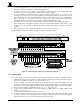
4. Connect the first switcher to the PC's COM port, via the null-modem adapter provided (see Note below
and Figure 1.
5. Make sure that the RS-232 cable is not more than 30 feet long.
6. If several machines are looped, interconnect as described in the relevant section below (12.4, 12.5, 12.6, or
12.7)
7. Connect the power cable of each switcher to the mains and turn them ON.
8. Activate the computer and the KRAMER K-Switch software. Then click the mouse button at the
appropriate location on the monitor display to operate all the switchers simultaneously.
NOTE
The KRAMER null-modem adapter is a small plug with two connectors: a DB-9 on one side and a DB-25 or DB-9 on
the other. We provide it with all switchers that have RS-232 ports. It interfaces between the DB-9 connector on the
switcher and the connector on the PC. Its function is to convert the PC output to a null-modem output and permit two
way communication between the switcher and the PC. This is effected by the interconnections within the plug.
12.4 Adding Outputs
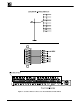
Two VS-1211 switchers may be interconnected to function as a 12x2 switcher by connecting the same
numbered sources to the same numbered inputs of both switchers. However, before doing so, each switcher
input has an internal jumper that must be properly set up to avoid double loading.
Proceed as follows:
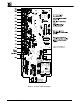
1. After disconnecting the switcher from the mains voltage, carefully remove the cover of the first switcher
that is to receive the source signals, remove jumpers J21 to J33 (for VS-1211) and relocate them in their
alternate positions (floating on the pin remote from the input socket and not connected in any circuit).
2. The input impedance of each input is now "High-Z" (not 75ohm terminated) and is therefore suitable for
this application. In the second switcher, the terminating jumpers stay in place, providing 75ohm
terminations. Thus, you do not have to open the second switcher. Carefully close the first switcher.