USER MANUAL MODEL: DS Vision® Digital HD Digital Distribution System P/N: 2900-300283 Rev 1
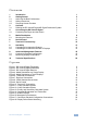
Contents 1 Introduction 1 2 2.1 2.2 2.3 3 3.1 Getting Started Achieving the Best Performance Safety Instructions Recycling Kramer Products Overview Defining the DS Vision® Digital HD Digital Distribution System 2 2 3 3 4 4 4 4.1 Connecting the DS Vision® Digital Connecting the Player and the Screen 7 7 5 5.1 6 Media Distribution Mounting the Receiver Serial Control 7 Terminal IP Connectivity 12 8 8.1 8.
1 Introduction Welcome to Kramer Electronics! Since 1981, Kramer Electronics has been providing a world of unique, creative, and affordable solutions to the vast range of problems that confront video, audio, presentation, and broadcasting professionals on a daily basis.
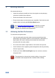
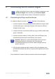
2 Getting Started We recommend that you: Unpack the equipment carefully and save the original box and packaging • materials for possible future shipment Review the contents of this user manual • • Ensure that the player and the screens are compatible. Check that they work together before connecting the DS Vision Digital system. i 2.1 Go to http://www.kramerelectronics.com to check for up-to-date user manuals, application programs, and to check if firmware upgrades are available (where appropriate).
2.2 Safety Instructions ! 2.3 Caution: There are no operator serviceable parts inside the unit Warning: Use only the Kramer Electronics input power wall adapter that is provided with the unit Warning: Disconnect the power and unplug the unit from the wall before installing Recycling Kramer Products The Waste Electrical and Electronic Equipment (WEEE) Directive 2002/96/EC aims to reduce the amount of WEEE sent for disposal to landfill or incineration by requiring it to be collected and recycled.
3 Overview DS Vision® Digital is a high-definition (HD) digital distribution system that delivers real-time digital, non-compressed content to digital signage terminals up to 600m (2000ft) away. DS Vision® Digital enables you to manage digital signage assets and monitor system performance. The DS Vision® Digital system offers the following high-level capabilities: 3.
3.1.1 The DS Vision® Digital Transmitter Figure 1: DS Vision® Digital Transmitter 3.1.
3.1.3 The DS Vision® Digital Receiver Figure 3: DS Vision® Digital Receiver 6 # Feature 1 12V DC POWER Connector Connects to the 12V DC power adapter Function 2 MONITOR 3.
4 Connecting the DS Vision® Digital i 4.1 Always switch off the power to each device before connecting it to your DS Vision® Digital. After connecting your DS Vision® Digital, connect its power and then switch on the power to each device. Connecting the Player and the Screen To connect the player to a screen, as Figure 4 illustrates, do the following: 1.
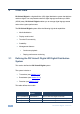
5 Media Distribution The DS Vision Digital system can distribute HD digital media from a single player to: • A single display located 100m (330ft) away, using the transmitter • Three displays located 100m (330ft) away, and one local display, using the broadcaster Figure 4 illustrates the configuration for media distribution to a single display: Figure 4: Media Distribution to a Single Display Figure 5 illustrates the configuration for media distribution to three displays: 8 DS Vision® Digital - Med
Figure 5: Media Distribution to Three Displays i Note! The connections to the transmitter and the broadcaster are identical. The broadcaster has three system ports and the transmitter has only one system port. All references to connections apply equally to both units. Figure 6 and Figure 7 illustrate all the connections to the DS Vision Digital units. Not all the connections are always needed. This section explains the basic connections.
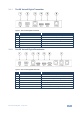
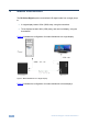
CAT5e cable from Transmitter System port 12 V Ethernet cable to network Receiver DC MONITOR SYSTEM HDMI ETHERNET CONTROL To Media Feedback Monitoring Engine Power connector HDMI cable to display Serial cable to display control Figure 7: Receiver Connections 5.1 Mounting the Receiver The receiver units have VESA standard screw holes 100mm (3.9in) apart, as shown in Figure 8. Use two screws supplied with the receiver and monitor to connect the unit to the back of the monitor.
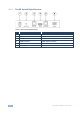
6 Serial Control To enable serial control of remote displays: 1. Connect a serial (9-pin D-sub male/female) cable between the players and the broadcaster/transmitter. 2. Connect a serial (9-pin D-sub female/female) cable between the receiver and the screen. Figure 9 illustrates the connections: Figure 9: Serial Control When using a broadcaster, the serial command is broadcasted to all the displays.
7 Terminal IP Connectivity To extend a network from the transmitter/broadcaster side to the remote terminal side: 1. Connect a standard Ethernet cable (Ethernet 10/100BaseT straight-through cable) between the player side network and the transmitter/broadcaster. 2. Connect a standard Ethernet cable (Ethernet 10/100BaseT straight-through cable) between the receiver and the terminal side units. Once these connections have been made, the extension system enables the creation of an extended IP segment.
8 Scalability There are two types of methods to extend the system scale: • Cascade a receiver with a broadcaster/transmitter to increase the distance of the system • Cascade a broadcaster with a broadcaster/transmitter to increase the number of supported displays 8.1 Cascading to Increase the Distance Cascade up to six distribution systems to increase the distance up to 600m (2,000ft). Figure 11 illustrates a 2-hop cascaded system.
Figure 12: 6-Hop Cascaded System 8.2 Cascading to Increase the Number of Displays Connect a primary broadcaster to a secondary broadcaster or transmitter to increase the number of receivers and displays that can be connected to the system. Cascading an additional broadcaster enables adding three displays, whereas cascading of an additional transmitter enables adding a single display. 1. Connect the primary broadcaster to a secondary unit using an HDMI to HDMI cable (type A, male/male). 2.
Figure 13: Primary and Secondary Cascaded System Figure 14 illustrates a system with two cascaded broadcasters and a transmitter, providing four additional displays: DS Vision® Digital - Scalability 15
Figure 14: Cascaded Broadcaster and Transmitter The system can be further scaled to include hundreds of displays.
Figure 15: Sixteen Displays When cascading to increase the distance, connect the receiver to the cascaded transmitter with the RS-232 serial cable. See Figure 11.
9 Advanced Management Features Use MDS management technology for advanced management features, such as: • Continuous playback (see Section 9.1) • Performance monitoring (see Section 9.2) Figure 16 illustrates the management architecture: Figure 16: Management Architecture To operate the management features, connect the transmitter/broadcaster to a DHCP server on the LAN. Once the transmitter/broadcaster is switched on, it receives an IP address from the DHCP server.
i Note: The receiver does not receive an IP address and is not visible as an IP network element. To learn more about the MDS management technology, features and benefits, refer to the ScreenGate Management Gateway documentation. 9.1 Continuous Playback Configuration Two active players can be connected to the DS Vision Digital system, one primary and the other secondary. If the primary player becomes unavailable the secondary player can be activated remotely, to enable continuous playback.
Figure 17: Continuous Playback Configuration Connections 9.2 Monitoring Display Performance A player can create a report that consists of the amount of times media was sent to the screen. However, this report can’t verify if the media was in fact displayed on the screen. The DS Vision Digital system uses a unique display performance monitoring mechanism embedded in the receiver unit to monitor and verify that the content played was actually displayed.
• In addition, a watermark generator agent must be installed on the player device.
10 Technical Specifications Feature Item Broadcaster Transmitter Receiver MAXIMUM RESOLUTION 1080p, 60Hz, 24bit per pixel, uncompressed 1080p, 60Hz, 24bit per pixel, uncompressed 1080p, 60Hz, 24bit per pixel, uncompressed VIDEO-1 HDMI HDMI compatible up to 10.2Gbps HDMI compatible up to 10.2Gbps HDMI compatible up to 10.
For the latest information on our products and a list of Kramer distributors, visit our Web site where updates to this user manual may be found. We welcome your questions, comments, and feedback. Web site: www.kramerelectronics.com E-mail: info@kramerel.