K R A ME R E LE CT R O N IC S L TD .
Contents 1 Introduction 1 2 2.1 2.2 2.3 2.4 Getting Started Achieving the Best Performance Safety Instructions Shielded Twisted Pair/Unshielded Twisted Pair Recycling Kramer Products 2 2 3 3 3 3 3.1 Overview Defining the WP-110xl UXGA/Data Line Transmitter 4 4 4 4.1 4.2 Connecting and Installing the WP-110xl Grounding the Wall Plate Wiring the TP LINE OUT RJ-45 Connector 6 7 8 5 5.1 5.
1 Introduction Welcome to Kramer Electronics! Since 1981, Kramer Electronics has been providing a world of unique, creative, and affordable solutions to the vast range of problems that confront video, audio, presentation, and broadcasting professionals on a daily basis.
2 Getting Started We recommend that you: Unpack the equipment carefully and save the original box and packaging materials for possible future shipment Review the contents of this user manual i 2.1 Go to http://www.kramerelectronics.com/support/product_downloads.asp to check for up-to-date user manuals, application programs, and to check if firmware upgrades are available (where appropriate).
2.2 Safety Instructions ! 2.3 Caution: There are no operator serviceable parts inside the unit Warning: Use only the Kramer Electronics input power wall adapter that is provided with the unit Warning: Disconnect the power and unplug the unit from the wall before installing Shielded Twisted Pair/Unshielded Twisted Pair We recommend that you use Shielded Twisted Pair (STP) cable, and stress that the compliance to electromagnetic interference was tested using STP cable.
3 Overview The WP-110xl is a high-performance, twisted pair (TP) transmitter for computer graphics signals over extended distances using CAT 5/6 cable. The transmitter can be connected to compatible receivers, such as, the PT-120xl, TP-122xl and the TP-126xl, (for 250m range), or the PT-120, TP-120, TP-120-od, TP-122, TP-122N, TP-122-od, TP-124, TP-124-od and the TP-124, (for 100m range). The WP-110xl comes in three models: the WP-110xl 69mm US version and the two WP-110xl 80/86mm European versions.
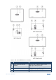
Figure 1: WP-110xl UXGA/Data Line Transmitter # Feature 1 PC IN 15-pin HD connector Connects to the computer graphics source 2 ON LED Lights green when powered on 3 +12V/GND Terminal Block Connects to the 12V DC power supply 4 LINE OUTPUT RJ-45 Connector Connects to the twisted pair receiver, (for example, the PT-120 or TP-126xl) 5 Ground Terminal Crimp terminal connects to earth WP-110xl - Overview Function 5
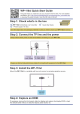
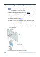
4 Connecting and Installing the WP-110xl i Always switch off the power to each device before connecting it to your WP-110xl. After connecting your WP-110xl, connect its power and then switch on the power to each device. To connect the WP-110xl as illustrated in the example in Figure 2: 1. Connect the LINE OUTPUT RJ-45 connector on the rear panel of the WP110xl to the TP receiver, (for example, the PT-120 or the TP-126xl). 2. Ground the wall plate, (see Section 4.1). 3.
4.1 Grounding the Wall Plate Grounding the WP-110xl is recommended. The grounding wire is connected to the rear of the chassis of the unit. The grounding screw is used to earth the unit to the ground of the building. This helps prevent static electricity from interfering with product performance. To connect the grounding to the WP-110xl as shown in Figure 3: 1. Crimp the ring-tongue terminal to the building grounding point wire. 2 (We recommend that you use a green-yellow #18 AWG wire (0.
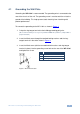
4.2 Wiring the TP LINE OUT RJ-45 Connector This section defines the TP pinout, using a straight pin-to-pin cable with RJ-45 connectors.
5 Capturing the EDID The WP-110x can capture an EDID from a connected display or can load a default EDID when no display is available or the unit cannot capture the EDID from the connected display. 5.1 Capturing the EDID from a Display Device To capture an EDID from a display: 1. Using a Philips screwdriver, remove the four screws holding the faceplate to the PCB assembly. 2.
5.2 Loading the Default EDID To load the default EDID: 1. Using a Philips screwdriver, remove the four screws holding the faceplate to the PCB assembly. 2. Do not connect a display to the PC IN input 15-pin HD connector. 3. Connect the 12V DC power adapter to the power terminal block (see Figure 1) on the WP-110xl and connect the adapter to the mains electricity. 4. Press the EDID capture button (item 1 on Figure 5 and Figure 6).
Figure 6: WP-110xl EU Wall Plate WP-110xl - Capturing the EDID 11
6 Technical Specifications INPUT: 1 VGA / UXGA on a 15-pin HD connector OUTPUT: 1 RJ-45 LINE OUTPUT connector VIDEO RESOLUTION: Up to WUXGA, 1080p RANGE: Up to 250m (820ft) COUPLING: AC POWER CONSUMPTION: 12V DC, 70mA OPERATING TEMPERATURE: 0° to +40°C (32° to 104°F) STORAGE TEMPERATURE: -40° to +70°C (-40° to 158°F) HUMIDITY: 10% to 90%, RHL non-condensing WALL PLATE SIZE: 2 gang EU/US DIMENSIONS: 2 gang USA: 11.4cm x 3.5cm x 11.4cm (4.49" x 1.4" x 4.49", W, D, H) 2 gang Europe: 15.
For the latest information on our products and a list of Kramer distributors, visit our Web site where updates to this user manual may be found. We welcome your questions, comments, and feedback. Web site: www.kramerelectronics.com E-mail: info@kramerel.