
Manual
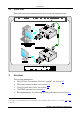
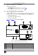
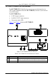
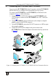
Table Of Contents

Connecting the PT-571HDCP and PT-572HDCP
7
7
5 Connecting the PT-571HDCP and PT-572HDCP
You can use the PT-571HDCP DVI Line Transmitter with the PT-572HDCP
DVI Line Receiver to configure a DVI transmitter/receiver system.
To connect the PT-571HDCP to the PT-572HDCP, as illustrated in the
example in
Figure 3, do the following:
1. Connect the CAT 5 OUT RJ-45 connector on the PT-571HDCP to the
CAT 5 IN RJ-45 connector on the PT-572HDCP via a CAT 5 cable (see
section
5.1).
2. On the PT-571HDCP, connect a DVI source (for example, a computer
graphics source) to the DVI IN connector.
3. On the PT-572HDCP, connect the DVI OUT connector to a DVI acceptor
(for example, a display).
4. Connect the 12V DC power adapter to the power socket on the
PT-571HDCP and connect the adapter to the mains electricity (not shown
in
Figure 3).
Figure 3: Connecting the PT-571HDCP / PT-572HDCP DVI Line Transmitter/Receiver