Kramer Electronics, Ltd.
Contents Contents 1 2 2.1 3 3.1 3.2 3.3 3.4 4 5 5.
Introduction 1 Introduction Welcome to Kramer Electronics! Since 1981, Kramer Electronics has been providing a world of unique, creative, and affordable solutions to the vast range of problems that confront the video, audio, presentation, and broadcasting professional on a daily basis. In recent years, we have redesigned and upgraded most of our line, making the best even better! Our 1,000-plus different models now appear in 11 groups 1 that are clearly defined by function.
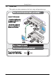
Getting Started 2.1 Quick Start This quick start chart summarizes the basic setup and operation steps.
Overview 3 Overview This section describes: • The power connect feature, see section 3.1 • Using shielded twisted pair (STP)/unshielded twisted pair (UTP), see section 3.2 • A summary of the TP-112HD, see section 3.3 • Recommendations for achieving the best performance, see section 3.4 3.1 About the Power Connect™ Feature The Power Connect feature applies as long as the cable can carry power. This feature is available when using STP cable and the distance does not exceed 50m on standard CAT 5 cable.
Your TP-112HD XGA/HD Line Transmitter – DA 3.3 About the TP-112HD Your Kramer TOOLS TP-112HD XGA/HD Line Transmitter - DA: • Receives a computer graphics 1/HD 2 signal and transmits it over two CAT 5 cables to appropriate receivers 3 • Has a transmission range of more than 300 ft. (more than 100 meters) • Includes the Power Connect feature • Is 12V DC fed 3.
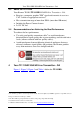
Your TP-112HD XGA/HD Line Transmitter – DA Figure 1: TP-112HD XGA/HD Line Transmitter – DA Figure 2: TP-112HD (Top Side Panel) Figure 3: TP-112HD (Lower Side Panel) Table 1: TP-112HD XGA/HD Line Transmitter - DA Features # Feature 1 12V DC 2 LINE OUT 2 RJ-45 Connector 3 LINE OUT 1 RJ-45 Connector 4 XGA/HD INPUT 15-pin HD Connector ON LED 5 Function +12V DC connector for powering the unit Connects to1 the LINE IN RJ-45 connector on the (second) TP-120 XGA Line Receiver 2 Connects to 1 the LINE IN RJ-
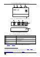
Configuring a 1:2 XGA/HD-to-Twisted Pair DA System Figure 4: TP-112HD (Underside Panel) Table 2: TP-112HD (Underside Panel) Features # Feature 1 VS Switch 2 5 HS Switch Function Slide the switch to the left 1 to change the VS polarity to NEGATIVE polarity 2; slide the switch to the right (to NORMAL) to retain the polarity Slide the switch to the left1 to change the HS polarity to NEGATIVE polarity2; slide the switch to the right (to NORMAL) to retain the polarity Configuring a 1:2 XGA/HD-to-Twisted Pai
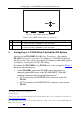
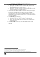
Configuring a 1:2 XGA/HD-to-Twisted Pair DA System 2. On the two TP-120 units, connect the: XGA OUT 15-pin HD connector of the first TP-120 unit to the XGA/HD acceptor (for example, display 1) XGA OUT 15-pin HD connector of the second TP-120 unit to the XGA/HD acceptor (for example, display 2) 3. On each of the three Kramer TOOLS, connect the 12V DC power adapter to the power socket and connect the adapter to the mains electricity.
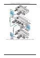
Configuring a 1:2 XGA/HD-to-Twisted Pair DA System Figure 5: Configuring a 1:2 XGA/HD to Twisted Pair Transmitter/Receiver/DA 8 KRAMER: SIMPLE CREATIVE TECHNOLOGY
Technical Specifications 5.
LIMITED WARRANTY Kramer Electronics (hereafter Kramer) warrants this product free from defects in material and workmanship under the following terms. HOW LONG IS THE WARRANTY Labor and parts are warranted for seven years from the date of the first customer purchase. WHO IS PROTECTED? Only the first purchase customer may enforce this warranty. WHAT IS COVERED AND WHAT IS NOT COVERED Except as below, this warranty covers all defects in material or workmanship in this product.
For the latest information on our products and a list of Kramer distributors, visit our Web site: www.kramerelectronics.com, where updates to this user manual may be found. We welcome your questions, comments and feedback. Safety Warning: Disconnect the unit from the power supply before opening/servicing. Caution Kramer Electronics, Ltd. Web site: www.kramerelectronics.com E-mail: info@kramerel.