
User Manual
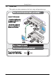
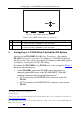
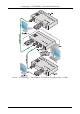

Configuring a 1:2 XGA/HD-to-Twisted Pair DA System
7
2. On the two TP-120 units, connect the:
XGA OUT 15-pin HD connector of the first TP-120 unit to the
XGA/HD acceptor (for example, display 1)
XGA OUT 15-pin HD connector of the second TP-120 unit to the
XGA/HD acceptor (for example, display 2)
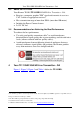
3. On each of the three Kramer TOOLS, connect the 12V DC power adapter
to the power socket and connect the adapter to the mains electricity.
The signal from the XGA source is transmitted via the two CAT 5 cables,
decoded and converted at the each of the XGA OUT 15-pin HD connectors
to the XGA acceptors.
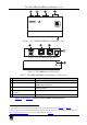
4. On the TP-120 units, if necessary:
Set the H SYNC and V SYNC switches
1
on the underside
Adjust
2
the video output signal level and/or cable compensation
equalization level
5. On the TP-112HD, if necessary, set the VS and HS switches
3
on the
underside
1 By default, both switches are set down (for negative V SYNC and H SYNC polarity)
2 Use a screwdriver to carefully rotate the trimmer, adjusting the appropriate level
3 By default, both switches are set to the right (to NORMAL) to retain the V SYNC and H SYNC polarity