
User Manual


Technical Specifications
9
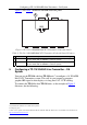
5.1 Wiring the CAT 5 LINE IN / LINE OUT RJ-45 Connectors
Table 3
and Figure 4 define the UTP CAT 5 PINOUT, using a straight pin
to pin cable with RJ-45 connectors:
Table 3: CAT 5 PINOUT
Figure 4: CAT 5 PINOUT
EIA /TIA 568A EIA /TIA 568B
PIN Wire Color PIN Wire Color
1 Green / White 1 Orange / White
2 Green 2 Orange
3 Orange / White 3 Green / White
4 Blue 4 Blue
5 Blue / White 5 Blue / White
6 Orange 6 Green
7 Brown / White 7 Brown / White
8 Brown 8 Brown
Pair 1 4 and 5 Pair 1 4 and 5
Pair 2 3 and 6 Pair 2 1 and 2
Pair 3 1 and 2 Pair 3 3 and 6
Pair 4 7 and 8 Pair 4 7 and 8
6 Technical Specifications
Table 4 includes the technical specifications
1
of the TP-114.
Table 4: Technical Specifications of the TP-114 (with 100m CAT 5 cable)
INPUT: 1 XGA on an 15-pin HD connector
OUTPUTS: 1 XGA on an 15-pin HD connector, 4 RJ-45 OUT connectors
MAX. OUTPUT LEVEL: 1.8Vpp (XGA), 1.6Vpp (CAT 5)
MAX. RESOLUTION
2
: UXGA, 1080P
DIFF. GAIN
2
: 0.03% (XGA), 7% (CAT 5)
DIFF. PHASE
2
: 0.05° (XGA), 0.08° (CAT 5)
K-FACTOR
2
: <0.05% (XGA), 0.3% (CAT 5)
S/N RATIO
2
: 75dB (XGA), 73dB (CAT 5)
CONTROLS
2
: 2 switches for sync inversion
COUPLING
2
: DC (XGA), AC (CAT 5)
POWER SOURCE: 12V DC, 880mA
3
DIMENSIONS: 12cm x 7.15cm x 2.76cm (4.7" x 2.8" x 1.08") W, D, H
WEIGHT: 0.3kg (0.67lbs) approx.
ACCESSORIES: Power supply
OPTIONS: RK-3T 19” rack adapter
1 Specifications are subject to change without notice
2 For the TP-114 Transmitter/ TP-120 Receiver pair
3 Sufficient for feeding two receivers via CAT 5