
Quick Start Guide
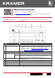
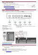
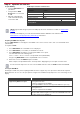

Table Of Contents

VM-4DT Quick Start
P/N:
2 9 0 0 - 3 0 0 7 9 9 QS
Rev:
2
Scan for full manual
VM-4DT Quick Start Guide
This guide helps you install and use your VM-4DT for the first time.
Go to www.kramerav.com/downloads/VM-4DT to download the latest user manual and check if firmware
upgrades are available.
Step 1: Check what’s in the box
VM-4DT 1:4 HDBT Distributor
1 Power adapter and cord
1 Quick start guide
4 Rubber feet
Step 2: Get to know your VM-4DT
#
Feature
Function
1
ON LED
Lights green when the unit receives power.
2
PROGRAM Mini USB Connector
Use to send RS-232 commands. Connect to a PC to perform firmware upgrades (via
K-Upload) and work with the EDID Designer. K-Upload and EDID Designer can be
downloaded from our Web site at:
www.kramerav.com/manual/EDID Designer.
To use the mini USB port, you need to download and the Kramer USB driver from our
Web site at:
www.kramerav.com/support/product_downloads.asp and install it.
3
EDID SETUP Button
Press to capture the input EDID, force RGB mode or select the default EDID.
4
ACTIVE INPUT LED
Lights green when an HDMI signal is embedded on the HDBaseT input.
5
HDBT LINK LEDs
IN
Lights green when a link is established with the HDBaseT transmitter.
OUT
Lights green when a link is established with the HDBaseT receiver (from 1 to 4).
Flashes when a non-HDCP acceptor is connected to the output and the input is
HDCP-encrypted (the content is displayed for only a few seconds).
6
OUTPUTS CONNECTED LEDs
Lights green when an acceptor (sink) is detected on the HDBaseT receiver connected
to the output (from 1 to 4).
7
INPUT HDBT Connector
Connects to an HDBaseT source, for example TP-580T.
8
HDBT OUT Connectors
Connect to an HDBaseT acceptor (from 1 to 4), for example TP-580R.
9
SETUP 8-way DIP-switches
Use to set IR (DIP-switches 1-4) and RS-232 (DIP-switches 5-8) command behavior.
10
SETUP 4-way DIP-switch
Always keep all four DIP-switches UP (off).
11
5V DC
+5V DC connector for powering the unit.