
Quick Start Guide
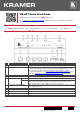
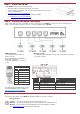
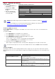

Table Of Contents

Step 3: Install the VM-4DT
Install VM-4DT using one of the following methods:
• Attach the rubber feet and place the unit on a flat surface.
• Fasten a bracket (included) on each side of the unit and attach it to a flat surface.
For more information go to
www.kramerav.com/downloads/VM-4DT.
• Mount the unit in a rack using the recommended rack adapter
(see
www.kramerav.com/product/VM-4DT).
Step 4: Connect the inputs and outputs
Always switch OFF the power on each device before connecting it to your VM-4DT. For best results, we recommend that you
always use Kramer high-performance cables to connect AV equipment to the VM-4DT.
HDBT RJ-45 Pinout:
Use a straight pin-to-pin cable with
RJ-45 connectors.
We recommend that for HDBT cables,
the ground shielding be
connected/soldered to the connector
shield.
DIP-Switch Setup:
To enable/disable IR and RS-232 routing, set the DIP-switches (by default,
set to OFF) as follows:
PIN EIA /TIA 568B
PIN
Wire Color
1
Orange / White
2
Orange
3
Green / White
4
Blue
5
Blue / White
Out #
IR Routing is enabled
when:
RS-232 Routing is enabled
when:
6
Green
7
Brown / White
OUT 1
DIP 1 – OFF (up)
DIP 5 – OFF (up)
OUT 2
DIP 2 – OFF (up)
DIP 6 – OFF (up)
OUT 3
DIP 3 – OFF (up)
DIP 7 – OFF (up)
For optimum range and performance use the
recommended Kramer cables available at
www.kramerav.com/product/VM-4DT.
OUT 4
DIP 4 – OFF (up)
DIP 8 – OFF (up)
Step 5: Connect the power
Connect the power adapter to the VM-4DT and plug the adapter into the mains electricity.
Safety Instructions
Caution:
There are no operator serviceable parts inside the unit.
Warning:
Use only the Kramer Electronics power supply that is provided with the unit.
Warning:
Disconnect the power and unplug the unit from the wall before installing.
See www.KramerAV.com for updated safety information.