Manual IP Camera MegaPixel User’s Manual Cod. KW.07 (Wired) Cod. KW.08 (Wireless) Warning The manufacturer is under no circumstances liable for any unauthorised modifications made to the product by the user or any other parties which may compromise its conformity and safety. www.kraun.
Manual Table of Contents 1. Introduction.................................................................................................................3 2. Hardware description and quick installation/usage................................................4 2.1. Major hardware components...................................................................................................4 2.2. Quick installation and usage.......................................................................................
Manual 1. Introduction The IP Camera is designed with the “user-friendly” idea deep in mind. The user can install the IP Camera easily on his/her home network and then access the IP Camera anywhere in the world through the accompanied video management software - KraunView program without setting some complicated DNS name or changing the router’s settings. It’s just a plug & play action. With 3GPP/ISMA support, users can see the video of the IP camera on any 3G mobile phone anywhere, anytime.
Manual 2. Hardware description and quick installation/usage The IP Camera is designed to be very easy to install and use. First, let’s see the major components of the IP Camera products. 2.1. Major hardware components. The major components on the front panel of the IP Camera products are the built-in microphone, lens and LEDs : 1. Microphone – for receiving the audio/voice. Effective distance is about 5 meters. 2.
Manual 3. Ethernet jack – this is the place to plug in the RJ45 Ethernet cable. When the Ethernet link is ok, the Ethernet indication LED on the front side will be blue light. 4. Reset button – this is the button to reset the IP Camera to default factory settings. You need to use a small stick like pencil or tooth stick to press the reset button for more than 3 seconds to enable the reset function.
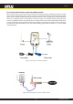
Manual First, Connect the IP Camera to the home/office network Please connect the IP Camera accessaries to the IP Camera body correctly, including the antenna, bracket, power adapter and Ethernet cable, as shown in Figure 2-3. And connect the other end of the Ethernet cable to the home network or office network. Usually, this Ethernet cable is plugged into a home NAT/router device or an Ethernet switch if in the office, as shown in Figure 2-4.
Manual Second, Install the KraunView software on the notebook/PC Please insert the installation CD into the CD-ROM drive in your notebook or personal computer (must be running Microsoft Windows OS). Execute the program KraunViewInstaller-xxx.exe on the disk. The program will pop-up some windows about the installation options, please press the “next” button to proceed with the installation.
Manual Seeing the video in a remote location After the IP Camera is installed and you can see the video from the KraunView software in the local network, it’s very easy to see the video in a remote location. All you need to do is add a camera item in the “CameraList” folder of the KraunView software, key in the IP CAM ID and Password(from the ID/Password card). And then double click this camera item. You will then see the Camera video immediately. No further NAT/router setting modifications are needed.
Manual 2.3. Wireless connection (for Cam(w)) The IP Camera can also be connected to the home/office network through the 802.11 b/g wireless connection. There are only three things that you need to do to have the wireless connection: 1. Set the WiFi security settings on the web configuration page. 2. Test if the WiFi settings are correct. 3. Unplug the Ethernet cable. First, set the WiFi security settings on the web configuration page. Make sure there is a WiFi router or AP on your home or office network.
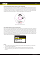
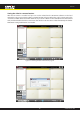
Manual 3. Web configurations You can login into the web configuration page by directly key-in the IP address of the IP Camera or right-click the searched IP Camera in the “Auto Search” list of the KraunView software and click the “Web Configure” to open the login window of the IP Camera. Figure 3-1: Open the web configuration page from KraunView software The default login account is “admin”, leave the Password field empty. Figure 3-2: IP Camera Web configuration login page 10 www.kraun.
Manual 3.1. Information The first page of the web configuration of the IP Camera is the information page. You can see the model name/firmware version, IP CAM ID, registration status, network type and current video settings( bandwidth, resolution) in this page. The IP Camera can be viewed remotely by the KraunView software only when the IP Camera is registered. If this IP Camera is not registered, please check the Ethernet wiring of your network environment.
Manual 3.2. Video Display This display page allows you to view the video display of the IP camera. For the first time use of this display on a computer, an activeX component will be automatically downloaded into the browser. This could take some time, depends on the internet speed. The component is downloaded from a public domain, so that the computer must be connected to the Internet. If you want to modify the video display screen size, please refer to section 3.6 for more details.
Manual 3.3. Network The Network page allows you to modify the network settings of the wired Ethernet. The default settings use DHCP to obtain an IP address automatically. In most of the home and office network environment, there is a DHCP server running. In this situation, by using this default settings, the IP Camera can work immediately in most of the time. If the Ethernet cable is unplugged, the IP Camera will lose connection.
Manual 3.4. WiFi security (For Cam(w)) You can use the wireless to connect the IP Camera to the network. If your network environment has a 802.11 b/g router or AP running, you can check the “Enable WiFi function” button to use the wireless. Figure 3-7: WiFi security disabled page In order to use the wireless network, you need to fill the following fields: 1. SSID – this is the ID of the wireless router or AP of your wireless network environment, must be set correctly. 2.
Manual All the fields in this page must be filled correctly with the same settings the wireless router or AP using. Figure 3-8: WiFi security enabled page You can also click the “WiFi test” button to check if the IP Camera can connect to the wireless network for these settings. You will need to unplug the Ethernet cable to enable the wireless connection after the “WiFi test” is successful. You can click the “WiFi scan” button to scan for all the available access points nearby.
Manual 3.5. Advanced Network In some special situation, your network environment only provides PPPoE connection(ADSL service), there is no NAT/router available. You will then need to set the PPPoE settings in the “Advanced Network” page. Only the PPPoE username and password are needed to let PPPoE work. After the “Save&Apply” button is pressed, the PPPoE function will work immediately.
Manual 3.6. Video Settings The IP Camera is designed to provide high quality video for viewing from KraunView software. In this page, you cam modify some settings related to the video viewing: 1. Password(play video) – this is the password needed for viewing the video from the KraunView software. Together with the IP CAM ID, you can view the video of this IP Camera anywhere in the world through the Internet. 2. Internet speed – this is the Internet bandwidth of your network environment.
Manual When this modification is “Save&Apply”ed, it works immediately, but all the connected video viewing users will be disconnected. Figure 3-11: Video settings page 18 www.kraun.
Manual 3.7. 3GPP/RTSP settings The IP Camera is able to be viewed from a 3G mobile phone, for detailed settings on the 3G mobile phone, please refer to Appendix E. Users can disable the 3G mobile access ability in this page. After the 3GPP/RTSP feature is disabled, no 3G mobile phone is allowed to access the video of the IP camera. When this is disabled, the rtsp stream with MPEG2 audio is still working, please refer to Appendix F for more details about rtsp stream with MPEG2 audio.
Manual 3.8. Email/ftp alarm The IP Camera provides the Email/ftp function, you can enable or schedule the Email/ftp ability in this page, the IP Camera product will then send out an email with a jpeg picture attached in the email and/or send out the jpeg picture file to a ftp server. The related settings are explained below: 1. Email/FTP trigger – choose between “motion”, “schedule” and “disable” A.
Manual When this modification is “Save&Apply”ed, it works immediately, but all the connected video viewing users will be disconnected. The default setting is “Disable”. Figure 3-13: Email/FTP Alarm page 21 www.kraun.
Manual 3.9. NAS settings The IP Camera provides the recording of the video files into a standard NAS ( Network Access Storage ) device. The IP camera connects to the NAS device using the standard LMX_NS/CIFS/SSN protocols that are the same as the Microsoft Windows network neighborhood protocols. This makes the IP camera easily record the video files to all the standard NAS devices in the market.
Manual In the Microsoft Windows environment, you can access to the NAS device by keying the URL address \\”NAS name”\”shared folder name” or \\”NAS IP address”\”shared folder name” in the windows Internet Explorer, and then key in the “NAS access account” and “NAS access password” to the prompted login window. The video files are recorded under the subfolder IPCamRecordFiles/Recording/ID-ID, where ID is the ID of this IP camera. All the recorded files are with the name of hhmmss.
Manual 3.10. Scheduling The IP Camera provides the scheduling function for the motion detection triggered email/ftp sending and/ or the NAS recording with the individual parameters set in the . “Email/ftp alarm” settings and the “NAS settings” page. Totally 12 schedule list items are allowed. There is no conflict check for the scheduling, it means that the scheduling time could be overlapped, and the IP camera will do all the scheduled events during the overlapped time period.
Manual 3.11. Led Display Control The IP Camera provides the Led Display Control function, you can enable or disable the led display/ indication on the front panel of the IP cam device. The related settings are explained below: 1. Normal led display – select this to enable the status led and ethernet led display. 2. Turn off led display always – select this to disable the status led and ethernet led display. 3.
Manual 3.12. Date/Time The IP Camera can synchronize the date/time with the universally available time server( for example stdtime.gov.tw) through NTP protocol. The date/time will then be corrected with the time server anytime when the Internet is connected. Users can choose the different TimeZone of their areas to display the correct time. For some TimeZone areas, the “Daylight Saving Time” could be enabled or disabled.
Manual 3.13. Admin In this page, you can modify the web login account. With this account, you can login to the IP Camera and do any modifications. The default account is “admin” without password. If the login account is forgotten, you can reset the IP Camera to the factory default settings by following the steps in section 3.15 and login with the “admin” account. Please be noticed that this account is different from the video play password in the “Video settings” page.
Manual 3.14. Upgrade If there is some new firmware available from the supplier of this IP Camera, you can upgrade the firmware on this page. Please ask for the correct information about FTP server, username/password account and firmware filename from your supplier, and then do this upgrade. A status message about the percentage done in the upgrade procedure is displayed.
Manual 3.15. Reboot You can restart the IP Camera manually on this page. All the connected video viewing users will be disconnected. Figure 3-21: System reboot settings page Figure 3-22: System reboot under-going page 29 www.kraun.
Manual 3.16. Safe Mode If by some abnormal operation, for example, powered off during the critical point of the upgrade procedure, the IP Camera will enter into the safe mode. In this mode, you will see the following “Safe mode” page when login into this IP Camera. Please do the upgrade operation immediately to recover the system. On this safe mode, the IP Camera can not display the video on the KraunView software, but you can still find this IP Camera on the “Auto search” list.
Manual 3.17. Set to factory default For some reason, for example you forgot the web login password, you may want to set the IP Camera to the factory default settings. The only thing you need to do is using a stick to press the “reset” button on the back of the IP Camera body for more than 4 seconds and release it, do this when the IP Camera is powered on. The IP Camera will reset to the factory default settings and restart automatically.
Manual 4. Features and specifications 4.1. Features • Easily access the camera from anywhere in the world via the ID/password • No complicated NAT/router settings needed. • Free video management software - KraunView program accompanied for easy access and multicamera management. • 3GPP/ISMA support for 3G mobile access. • Dual video streaming with separate frame rate/resolution/bandwidth settings for PC and mobile. • Built-in Web server for managing via standard web browser.
Manual 4.2. Specifications Models IP Camera Power DC 5V, 1A Processors RISC CPU, hardware video processing and compression. Network interface Ethernet 10BaseT/100BaseTX, Auto-MDIX, RJ-45 Wireless interface (for Cam(w) only) IEEE 802.11g 6 - 54 Mbps IEEE 802.11b 1 - 11 Mbps Transmit power: 14.5dBm typically @ 802.11g 17.5dBm typically @ 802.11b Receiver sensitivity: 54Mbps: Typical -73dBm @ 10% PER 11Mbps: Typical -86dBm @ 10% PER Modes: Infrastructure and ad-hoc Antenna gain: 1.
Manual Minimum Web browsing and management software requirements Built-in web server for standard web browser access Pentium 4 CPU 1.0 GHz or higher, or equivalent AMD 1 GB RAM Supported protocols IPv4, HTTP, TCP, ICMP, RTSP, RTP, UDP, IGMP, RTCP, SMTP, SNTP, FTP, DHCP, UPnP, ARP, DNS, PPPoE, etc. Accessories (included) Power adaptor, camera bracket, RJ45 ethernet cable, quick installation guide, CD with installation tool/software and User’s Manual, ID/Password card, antenna(for Cam(w)).
Manual 5. FAQ. 1. What’s going on when the red led light on the IP camera is flashing? A: When the IP Cam is connected to the Internet and working correctly, the red led light will be on constantly. If the red led light is flashing, it’s probably because there is some network connecting problem. Please check the network connection again and follow the instructions on the user manual to set it up again. 2.
Manual 9. Does the IP Cam provide the recording function? A: You can do the recording of the video/audio of the IP Cam from the KraunView software with the KraunView software. You can also do the video/audio recording to the standard NAS storage device. Another software CamPlay is needed to playback the recorded vide/audio files. 10.