THE LEADER IN AUDIO ENGINEERING Showcase 7 Showcase 6 Showcase 5 Multichannel Amplifier Instructions for Use Owner’s Reference
Showcase 7 Showcase 6 Showcase 5 Multichannel Amplifier Instructions for Use v 02.1 CONTACT INFORMATION Krell Industries, Inc. 45 Connair Road Orange, CT 06477-3650 USA TEL 203-799-9954 FAX 203-891-2028 E-MAIL krell@krellonline.com WEBSITE http://www.krellonline.com This product complies with the EMC directive (89/336/EEC) and the low-voltage directive (73/23/EEC). WARNINGS The amplifier must be placed on a firm, level surface where it is not exposed to dripping or splashing.
Contents Page Krell Showcase Amplifier INTRODUCTION 1 DEFINITION OF TERMS 2 UNPACKING 3 PLACEMENT AC Power Guidelines 4 4 FRONT PANEL DESCRIPTION 6 BACK PANEL DESCRIPTION 8 CONNECTING THE SHOWCASE AMPLIFIER TO YOUR SYSTEM Input and Output Connections 10 10 AMPLIFIER OPERATION On/Off and Operation 12 12 TROUBLESHOOTING SYSTEM NOISE 13 QUESTIONS AND ANSWERS 14 WARRANTY 15 RETURN AUTHORIZATION PROCEDURE 16 SPECIFICATIONS 17 iii
Illustrations Page iv FIGURE 1 The Showcase Amplifier Front Panel 5 FIGURE 2 The Showcase Amplifier Back Panel 7 Krell Showcase Amplifier
Introduction Thank you for your purchase of a Krell Showcase Amplifier. The Showcase Amplifier is a flexible design that delivers five, six, or seven channels of amplification. All three configurations include input and output connections for all seven channels. The amplifiers differ only by how many channels are housed within the amplifier. A Showcase 5 includes five amplifier channels, a Showcase 6 includes six amplifier channels, and a Showcase 7 includes seven amplifier channels.
Definition of Terms Following are the definitions of key terms used in your owner’s reference manual. INPUT AND OUTPUT CONNECTIONS Balanced A symmetrical input or output circuit that has equal impedance from both input terminals to a common ground reference point. The industry standard for professional and sound recording installations, balanced connections have 6 dB more gain than single-ended connections and allow the use of long interconnect cables.
Unpacking 1. Open the shipping box, and remove the top layer of foam. The following items are visible: 1 Showcase Amplifier 1 Accessory Kit containing: 1 1 1 1 1 1 IMPORTANT AC power cord 12 VDC output (12 V trigger) cable spare AC mains fuse 10 A slow-blow fuse for 100 –120 VAC 5 A slow-blow fuse for 220 –240 VAC packet containing the owner’s reference manual and the warranty registration card. Two people are needed to remove the amplifier from the shipping box. 2.
Placement Before you integrate the Showcase Amplifier into your system, review the following guidelines to choose the location for the component. This will facilitate a clean, trouble-free installation. The Showcase Amplifier requires at least two inches (5 cm) of clearance on each side and at least two inches (5 cm) of clearance above and below the component to provide adequate ventilation. The Showcase Amplifier does not require any type of special rack or cabinet for installation.
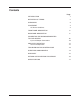
Figure 1 The Showcase Amplifier Front Panel S H O W C A S E AMPLIFIER STAND-BY POWER 3 2 1 1 Power Button 2 Stand-by LED 3 Power LED
Front Panel Description See Figure 1 on page 5 The Showcase Amplifier front panel provides power on and indicates operating status. 1 Power Button Use this button to switch the Showcase Amplifier power between the stand-by and the operational modes and also to switch the 12 VDC output (12 V trigger) on and off. 2 Stand-by LED The red stand-by LED illuminates when the AC power cord is plugged into the wall. The stand-by LED flashes when the protection circuit is activated.
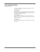
Figure 2 The Showcase Amplifier Back Panel 7 INPUT 1 INPUT 2 INPUT 3 INPUT 5 INPUT 4 INPUT 6 INPUT 7 8 12VDC OUT 5 IN 30mA max. 4 Showcase Multi-channel Amplifier 6 OUTPUT 1 OUTPUT 2 OUTPUT 3 OUTPUT 4 OUTPUT 5 OUTPUT 6 OUTPUT 7 50/60 Hz KRELL INDUSTRIES, INC.
Back Panel Description See Figure 2 on page 7 The Showcase Amplifier back panel provides connections for all inputs and outputs, remote connection input and output links, and the AC power supply. BALANCED INPUTS 4 Inputs 1-7 The Showcase Amplifier has seven channel inputs for output devices with balanced XLR connectors. SINGLE-ENDED INPUTS 5 Inputs 1-7 The Showcase Amplifier has seven channel inputs for output devices with single-ended RCA connectors.
Back Panel Description, continued BACK PANEL REMOTE CONNECTIONS, continued 8 12 VDC Remote Power In The Showcase Amplifier is equipped with an input that receives 12 VDC power on/off (12 V trigger) signals from other Krell components and other devices that incorporate a 12 V trigger. This allows you to turn the Showcase Amplifier on and off using a Krell or other component in a custom installation.
Connecting the Showcase Amplifier to Your System INPUT AND OUTPUT CONNECTIONS The Showcase Amplifier is equipped with balanced and single-ended inputs. Krell recommends using balanced interconnect cables. Balanced interconnect cables not only can minimize sonic loss but are also immune to induced noise, especially with installations using long cables. Balanced connections have 6 dB more gain than singleended connections. When level matching is critical, please keep this gain value in mind.
Connecting the Showcase Amplifier, continued INPUT AND OUTPUT CONNECTIONS, continued 4. Connect the loudspeaker cables to the Showcase Amplifier channel output binding posts (6) located on the back panel. The Showcase 5 uses only outputs 1-5 and has caps on the speaker binding posts for channels 6 and 7. The Showcase 6 uses outputs 1-6 and has caps on the speaker binding posts for channels 6 and 7. The binding post terminals accept spade lugs, bare wire, or pins.
Amplifier Operation ON/OFF AND OPERATION When powering up your system, turn the amplifiers on last. When powering down your system, turn amplifiers off first. The procedures for amplifier operation follow. 1. Plug the end of the AC power cord into the AC wall outlet. 2. The red stand-by LED (2) illuminates. When the amplifier is first plugged in, there is a brief delay before it can be put in the operational mode. Please wait approximately 10 seconds.
Troubleshooting System Noise When you mix and match high-performance audio components, each with its own ground potential, a low frequency hum may occur in one or all loudspeakers. If this happens when you place the Showcase Amplifier into your system, follow these simple troubleshooting steps: 1. Check that all input and output connections are of sound construction. 2. With the amplifier off, remove all the interconnect cables, then turn the amplifier on.
Questions and Answers Q. Should I turn the Showcase Amplifier off (unplug the amplifier) when not playing music? A. No. Leave the Showcase Amplifier in the stand-by mode when not playing music. The stand-by mode avoids cold starts as well as minimizes heat output and power consumption. Turn the amplifier off if you plan to be away for a period of time, for example, on vacation. See Amplifier Operation, on page 12. Q. When I turn the amplifier on there is a loud hum through the loudspeakers.
Warranty To register your product for warranty benefits, please complete and return the Warranty Registration Card enclosed in the shipping box within 15 days of purchase. Thank you. This Krell product has a limited warranty of five years for parts and labor on circuitry. Should this product fail to perform at any time during the warranty, Krell will repair it at no cost to the owner, except as set forth in this warranty. The warranty does not apply to damage caused by acts of God or nature.
Return Authorization Procedure HOW TO EXPEDITE SERVICE If you believe there is a problem with your component, please contact your dealer, distributor, or the Krell factory to discuss the problem before you return the component for repair. To expedite service, you may wish to complete and e-mail the Service Request Form in the Service section of our website at: http://www.krellonline.
Specifications Showcase 7, Showcase 6, Showcase 5 Showcase 7 Showcase 6 Showcase 5 20 Hz to 20 kHz +0 dB, -0.15 dB 20 Hz to 20 kHz +0 dB, -0.15 dB 20 Hz to 20 kHz +0 dB, -0.15 dB .2 Hz to 95 kHz +0 dB, -3 dB .2 Hz to 95 kHz +0 dB, -3 dB .2 Hz to 95 kHz +0 dB, -3 dB >110 dB >110 dB >110 dB GAIN 26.2 dB 26.2 dB 26.2 dB TOTAL HARMONIC DISTORTION (THD) 1 kHz < 0.03% 20 kHz < 0.20% 1 kHz< 0.03% 20 kHz< 0.20% 1 kHz < 0.03% 20 kHz < 0.
Krell Industries, Inc. 45 Connair Road Orange, CT 06477-3650 USA TEL 203-799-9954 FAX 203-891-2028 E-MAIL krell@krellonline.com WEBSITE http://www.krellonline.com Showcase 7 Showcase 6 Showcase 5 Multichannel Amplifier v 02.