THE LEADER IN AUDIO ENGINEERING Home Theater Standard 7.
Home Theater Standard 7.1 Surround Preamp/Processor Instructions for Use v 02.3 CONTACT INFORMATION Krell Industries, Inc. 45 Connair Road Orange, CT 06477-3650 USA TEL 203-799-9954 FAX 203-891-2028 E-MAIL krell@krellonline.com WEBSITE http://www.krellonline.com This product complies with the EMC directive (89/336/EEC) and the low-voltage directive (73/23/EEC). WARNINGS The Home Theater Standard 7.1 must be placed on a firm level surface where it is not exposed to dripping or splashing.
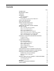
Contents Page INTRODUCTION 1 DEFINITION OF TERMS 2 UNPACKING 4 PLACEMENT 5 AC Power Guidelines GETTING STARTED An Introduction to System Setup and Operation FRONT PANEL DESCRIPTION 6 6 8 BACK PANEL DESCRIPTION 14 REMOTE CONTROL DESCRIPTION Battery Installation and Removal 17 17 CONNECTING THE HOME THEATER STANDARD TO YOUR SYSTEM 22 Step 1: Power Off and Prepare Wiring Step 2: Connect Analog Sources Step 3: Connect Digital Sources Step 4: Match Video Formats and Signals Step 5: Connect Video
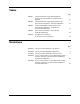
Tables Page TABLE 1 TABLE 2 TABLE 3 TABLE 4 TABLE 5 Factory Default Video Inputs and Standards for the Home Theater Standard 7.1, North American Operation 41 Factory Default Video Inputs and Standards for the Home Theater Standard 7.1, International Operation 41 Factory Default Digital and Analog Inputs for the Home Theater Standard 7.1, North American and International Operation 43 Home Theater Standard 7.
Introduction Thank you for your purchase of the Krell Home Theater Standard 7.1 Surround Preamp/Processor. The Home Theater Standard 7.1 surround preamp/processor serves as the centerpiece in a Krell HEAT™—High End Audio Theater— system, which applies the fundamental principles of Krell engineering to the creation of a fully integrated high-performance multichannel sound system. The Home Theater Standard 7.
Definition of Terms Following are the definitions of key terms used in your owner’s reference manual: INPUT AND OUTPUT CONNECTIONS Balanced A symmetrical input or output circuit that has equal impedance from both input terminals to a common ground reference point. The industry standard for professional and sound recording installations, balanced connections have 6 dB more gain than single-ended connections and allow the use of long interconnect cables.
Definition of Terms, continued TECHNOLOGY Krell Current Mode A proprietary Krell circuit topology in which the audio gain stages of a component operate in the current rather than the voltage domain. This unique technology provides the component with exceptional speed and a wide bandwidth. Krell HEAT The Krell term HEAT, or High End Audio Theater, is a design application incorporated into Krell components to enhance multi-channel home entertainment systems.
Unpacking Open the box and remove the top layer of foam. You see these items: 1 Home Theater Standard 7.1 1 IEC connector (AC power) cord 1 Home Theater Standard 7.1 handheld remote control 1 CR2025 lithium battery 1 T-15 Torx wrench (small L type) 1 T-10 Torx wrench (small L type) 1 12 VDC output (12 V trigger) cable 1 packet containing the owner’s reference manual, the “read this first” insert, and the warranty registration card. Carefully remove the unit and accessories from the box.
Placement Before you install the Home Theater Standard 7.1 into your system, review the following guidelines to choose the location for the component. This will facilitate a clean, trouble-free installation. The Home Theater Standard 7.1 does not require any type of special rack or cabinet for installation. For the dimensions of your Home Theater Standard 7.1 see Specifications, on pages 80-81. The Home Theater Standard 7.
Getting Started AN INTRODUCTION TO SYSTEM SETUP AND OPERATION The Home Theater Standard 7.1 provides comprehensive connection and operation options for outstanding music and cinema soundtrack reproduction. To take full advantage of the features the Home Theater Standard 7.1 offers, we recommend that you set up your system for operation in the following order: 1. Review the features of the Home Theater Standard 7.1.
LD TUNER CD 3 2 1 HTS Device Selection Buttons and LEDs 5 DVD Button and LEDs 6 LD Button and LEDs 7 SAT Button and LEDs 8 VCR1 Button and LEDs Basic Operation 1 Power Button 2 Power LED 3 Stand-by LED 4 Infrared Sensor POWER AUX2 AUX1 TV 15 17 ZONE 16 31 RECALL TV Button and LEDs CD Button and LEDs Tuner Button and LEDs Aux1 Button and LEDs Aux2 Button and LEDs Tape/VCR2 Button and LEDs Main Zone and Zone 2 Button 16 Main Zone and Zone 2 LEDs 17 Infrared Emitter 9 10 11 12 13 14 15 29 D
Front Panel Description See Figure 1 on page 7 FEATURES The Home Theater Standard 7.1 front panel provides power on and off; input, zone, and processing mode selection; monitoring and display of processor status; and balance and volume control. The front panel features are described below: Basic Operation Buttons 1 Power Button The power button switches the Home Theater Standard 7.1 from the stand-by to the operational mode. Note When you power off while zone 2 is selected, only zone 2 turns off.
Front Panel Description, continued Device Selection Buttons and LEDs, continued 8 VCR Button and LED Use this button to select the VCR device. 9 TV Button and LED Use this button to select the television device. 10 CD Button and LED Use this button to select the compact disc device. 11 Tuner Button and LED Use this button to select the AM/FM tuner device. 12 Aux1 Button and LED Use this button to select an auxiliary device, such as phono, tape, or an additional DVD, LD, CD, or VCR.
Front Panel Description, continued Processing Mode Buttons and LEDs 18 Stereo Button and LED Use this button to select stereo decoding, in order to make an A/B comparison or listen to a stereo recording in two channel format (left and right). The red LED illuminates when this feature is engaged. After you select a mode, press the stereo button once. Press the stereo button again to make the A/B comparison. Press the stereo button again to exit stereo format.
Front Panel Description, continued Processing Mode Buttons and LEDs, continued 23 THX Button Use this button to select one of the various THX modes available for the current signal. Display 24 Front Panel Display The front panel window provides status messages for Home Theater Standard 7.1 operations, including volume and balance level, decoding mode and zone information. In addition, when a new device is selected, the physical inputs are displayed. The display turns off after 60 seconds of inactivity.
Front Panel Description, continued Processor Function Buttons 29 Save Button Press and hold this button to save system configuration settings. The save button is also used in programming a learning remote. See Saving and Recalling Customized Settings and Restoring the Factory Default System Settings, on page 70, and Program Remote, on page 64.
ANALOG AUDIO OUTPUTS SL SB L SR SB R L R C SB L SB R SW SL C SW SR L R 33 7.
Back Panel Description See Figure 2 on page 13 FEATURES The back panel of the Home Theater Standard 7.1 provides all audio and video input and output connections, remote control inputs and outputs, power on and off, and power connection. The back panel functions are described below. Analog Audio Outputs and Inputs 32 Balanced Analog Audio Outputs The Home Theater Standard 7.
Back Panel Description, continued Analog Audio Outputs and Inputs, continued 42 7.1 Audio Inputs The Home Theater Standard 7.1 is equipped with eight single-ended 7.1 inputs for multichannel SACD and DVD audio devices. These inputs currently act as analog pass-through inputs, with no mode processing capabilities. Digital Audio Inputs and Outputs 43 Optical Digital Audio Inputs The Home Theater Standard 7.1 is equipped with two optical digital EIAJ inputs with TosLink connectors.
Back Panel Description, continued Video Inputs and Outputs, continued 51 Component Video Inputs The Home Theater Standard 7.1 is equipped with two sets of component video inputs. Note On-screen display (OSD) is not available for progressive component video. OSD is available for interlaced component video. Back Panel Remote Control Connections 52 Comm Port RS-232 Connector The Home Theater Standard 7.
Figure 3 The Home Theater Standard 7.
Remote Control Description See Figure 3 on page 17 The Home Theater Standard 7.1 remote control provides on and off, input selection, processing mode selection, speaker volume and balance adjust, and mute functions, as well as access to the system configuration menu. To send operational instructions directly to the Home Theater Standard 7.
Remote Control Description, continued Zone Selection Keys 59 Main Key Use this key to select the main zone for a device. 60 Z2 Key Use this key to select zone 2 for a device. Note The main zone is the factory default. To activate a device in zone 2, press the remote control Z2 key (60) before selecting the device. For other main zone and zone 2 operating options, see Main Zone and Zone 2 Operation, on page 72. Device Selection Keys 61 DVD Key Use this key to select the digital videodisc device.
Remote Control Description, continued Processing Mode Keys 71 Stereo Key Use this key to select stereo decoding, which allows you to make an A/B comparison or listen to a stereo recording in two channel format (left and right). The red LED illuminates when this feature is engaged. After you select a mode, press the stereo button once. Press the stereo button again to make the A/B comparison. Press the stereo button again to exit stereo format.
Remote Control Description, continued Control Function Keys 76 Bal Key (Balance Key) Press and hold this key to convert the volume level controls to balance controls. See Balance Button (28), on page 11. Note Use the center, surr/back, and sub keys to change taste trims to make temporary loudspeaker output adjustments of +/- 10 dB. These changes revert to 0 dB when a new source is selected or the system is powered down. See Configure Level Adjustment, on page 49.
Connecting the Home Theater Standard 7.1 to Your System This section provides information about connecting the Home Theater Standard 7.1 to your system. To expedite setup, please review Getting Started, on page 6, before following the connection steps below. CONNECTION STEPS Follow these steps to connect the Home Theater Standard 7.1 to your system: Step 1: Power Off and Prepare Wiring 1. Make sure all power sources and components are off before connecting inputs and outputs. 2.
Connecting the Home Theater Standard 7.1 to Your System, continued Step 3: Connect Digital Sources The Home Theater Standard 7.1 is equipped with six coaxial digital audio inputs (44) via RCA connectors and two digital EIAJ optical inputs (43) via TosLink connectors. Connect the digital audio output of your source components to the digital inputs on the Home Theater Standard 7.1.
Connecting the Home Theater Standard 7.1 to Your System, continued Step 4: Match Video Formats and Signals To match the video formats and signals in your system, we recommend that you follow these steps: 1. Determine your monitor format. The factory default video format in North America is NTSC Interlaced. The factory default video format overseas is either NTSC Interlaced or PAL Interlaced. 2. Look at the back panel of the video source, to determine which video signals you have available.
Connecting the Home Theater Standard 7.1 to Your System, continued C o N mp TS o C sit In e 1 te rla ce d SV N TS ide C o1 In te rla ce d SV N TS ide C o2 In te rl C om ace N d TS po C sit In e 3 C terl (T o N mp ace AP TS E) os d C i In te 2 te rla ce d C o N mp TS o C ne In nt te 1 rla ce d Figure 4 Device Selection Buttons, Factory Default Video Signals, and Video Formats for the Home Theater Standard 7.
Connecting the Home Theater Standard 7.1 to Your System, continued Figure 5 Device Selection Buttons, Factory Default Video Signals, and Video Formats for the Home Theater Standard 7.
Connecting the Home Theater Standard 7.1 to Your System, continued Step 5: Connect Video Sources and the Video Monitor The Home Theater Standard 7.1 is equipped with component, s-video, and composite connections. We recommend that you use the component connection to the Home Theater Standard 7.1, wherever the video source and video monitor both feature component connections. See the user manuals included with these sources for more information. Video inputs for the Home Theater Standard 7.
Connecting the Home Theater Standard 7.1 to Your System, continued Step 5: Connect Video Sources and the Video Monitor, Follow these steps to connect the Home Theater Standard 7.1 to the video sources and monitor in your system: continued 1. Connect the video outputs on each video source in your system to video inputs on the Home Theater Standard 7.1. 2. Connect the video outputs on the Home Theater Standard 7.1 labeled OSD to the inputs of the video monitor.
Connecting the Home Theater Standard 7.1 to Your System, continued Step 6: Activating the On Screen Display (OSD), Follow these troubleshooting steps, if the OSD is not visible after you follow the above activation steps 1 through 5: continued Troubleshooting the OSD 1. Check the AC connections and the video source and monitor connections to the Home Theater Standard 7.1 2. Match the video format and signal. (For example, component to component and NTSC to NTSC.) 3.
Connecting the Home Theater Standard 7.1 to Your System, continued Step 6: Activating the On Screen Display (OSD), continued Video Source Connection Scenarios, continued EXAMPLE 3: You want to use an s-video connection with a VCR device and you reside in Europe. Connect the VCR device to the Home Theater Standard 7.1 and connect the Home Theater Standard 7.1 to the PAL Interlaced video monitor using s-video (OSD) connections.
Connecting the Home Theater Standard 7.1 to Your System, continued Step 7: Connect Amplifiers and Loudspeakers The Home Theater Standard 7.1 has balanced outputs with XLR connectors, single-ended outputs with RCA connectors, and is equipped with a DB-25 multichannel output. These output formats are active at all times, allowing simultaneous connection to separate amplifiers. Use only one output format per amplifier.
Overview: System Configuration and Navigation This section briefly outlines the configuration menus and introduces the navigational features of the menus. To expedite setup, connect your entire system before configuring the Home Theater Standard 7.1. Match video signals and activate the on screen display (OSD) before attempting to access the configuration menu. See Connecting the Home Theater Standard 7.1 to Your System, on page 22.
Overview: System Configuration and Navigation, continued NAVIGATION CONVENTIONS The remote control is the main input device for configuring the Home Theater Standard 7.1. For all system options, use the following keys to navigate through the configuration menu screens: 82 Menu Key Press once to enter the configuration menu. The front panel display reads MENU MODE. The MAIN MENU screen appears. The HTS 7.1 reverts to the operational mode. Press this key again to exit the configuration menu.
System Configuration The Home Theater Standard 7.1 is shipped with factory default selections in the configuration menus. For maximum performance, the Home Theater Standard needs to be configured for each system device, its capabilities, and loudspeaker positions in the listening room. To save your new configuration menus, or revert to the factory defaults, see Saving and Recalling Customized Settings, and Restoring the Factory System Settings, on page 70.
System Configuration, continued STEP 1 CONFIGURE LOUDSPEAKERS The first option on the main menu screen, CONFIGURE SPEAKERS, lets you tell the Home Theater Standard 7.1 how many and what type of loudspeakers are in your system and select the bass range for each loudspeaker. It also allows you to control the subwoofer output and set the crossover frequency. Select CONFIGURE SPEAKERS on the MAIN MENU.
System Configuration, continued Speaker Setup Screen, continued Using this screen, you can enable loudspeakers that are in your system in the left column and select loudspeaker characteristics in the far right column. FULL RANGE sends 20Hz to 20KHz signals to the loudspeaker. LIMITED sends information from the crossover frequency (see below) to 20KHz to the loudspeaker.
System Configuration, continued STEP 2 LISTENING ROOM SETUP The second option on the main menu screen, ROOM SETUP, allows you to tell the Home Theater Standard 7.1 the exact location of each loudspeaker in your system. Select LISTENING ROOM SETUP on the MAIN MENU. The ROOM SETUP screen appears, with the cursor blinking at LEFT.
System Configuration, continued STEP 3 CALIBRATE VOLUME The third option on the main menu screen, CALIBRATE VOLUME, allows you to calibrate each channel using the internal noise generator of the Home Theater Standard 7.1, either automatically, manually, or by listening to external program material. Note A sound pressure level (SPL) meter is required for this procedure. Select CALIBRATE VOLUME on the MAIN MENU. The CALIBRATE ROOM SETUP screen appears, with the cursor blinking at AUTO NOISE SEQUENCE.
System Configuration, continued Set the SPL meter to C weighting and slow response. After initializing, the LEFT channel dB setting on the screen blinks, and you hear band limited white noise through the left loudspeaker. This noise continues for two seconds and then moves clockwise to the next loudspeaker in the system. While the individual channel on screen is blinking, use the direction keys to adjust each loudspeaker’s setting until the SPL meter reads 75 dB.
System Configuration, continued Please read before continuing on to Step 4 To help you understand the numerous configuration options available through the Home Theater Standard 7.1, Step 4 illustrates configuring a specific source device: a DVD player. To configure other source devices, Krell recommends that you configure one device at a time, using the menu’s step-by-step format. IMPORTANT Some Home Theater Standard 7.
System Configuration, continued Please read before assigning video inputs The Home Theater Standard 7.1 is shipped with separate factory default video inputs and standards for North American and international operation. See Table 1 and Table 2 below. Table 1 Factory Default Video Inputs and Standards for the Home Theater Standard 7.
System Configuration, continued Assign Video Input Select CONFIGURE VIDEO from the CONFIGURE DEVICES menu. The ASSIGN VIDEO INPUT screen appears, with the cursor blinking at DVD. Assign Video Input Screen KRELL HTS -ASSIGN VIDEO INPUTDEVICE DVD ASSIGN INPUT COMPONENT 1 VIDEO STANDARD NTSC INTERLACED The ASSIGN VIDEO INPUT screen lets you select the device to configure and assign an input to the device. Assigned inputs correspond to the inputs on the back panel.
System Configuration, continued The Home Theater Standard 7.1 is shipped with factory defaults for analog and digital inputs. These defaults are the same for domestic and international operation, and are listed in Table 4 below: Please read before configuring audio and digital inputs Table 3 Factory Default Digital and Analog Audio Inputs for the Home Theater Standard 7.1, North American and International Operation g Digital Analog p Digital Analog Dolby Digital 2.0 Dolby Digital 5.1 DTS 5.
System Configuration, continued Table 4 Home Theater Standard 7.1 Factory Default Audio Operating Modes Possible Default Operating Modes Digital Signals (4 formats) Analog Signal Dolby Digital 2.0 Dolby Digital 5.1 Dolby D + PLII Movie Dolby D + PLII Movie + THX Dolby D + PLII Music Dolby D + PLII Matrix Dolby D + Dolby Pro Logic Dolby D + Pro Logic + THX Dolby D 2.0 Dolby D 5.1 Dolby Digital EX1 Dolby D 5.1 + THX Dolby D 5.
System Configuration, continued Assign Analog Audio Inputs Select CONFIGURE AUDIO from the CONFIGURE DEVICES menu. The ASSIGN AUDIO INPUTS screen appears, with the cursor blinking at ANALOG. Assign Audio Inputs Screen KRELL HTS -ASSIGN AUDIO INPUTS ANALOG DIGITAL Select ANALOG. The ASSIGN ANALOG AUDIO INPUT screen appears, with the cursor blinking at DVD.
System Configuration, continued Assign Digital Audio Inputs Select DIGITAL from the ASSIGN AUDIO INPUTS screen. The ASSIGN DIGITAL AUDIO INPUTS screen appears, with the cursor blinking at DVD. Assign Digital Audio Input Screen KRELL HTS -ASSIGN DIGITAL AUDIO INPUTDEVICE DVD COAX 1 INCOMING SIGNAL DOLBY D 5.1 DEFAULT MODE DOLBY D 5.
System Configuration, continued Configure Trigger The final option on the CONFIGURE DEVICES menu is CONFIGURE TRIGGER. This option allows you to customize the operation of the four remote output 12 VDC (12 Volt trigger) connectors (54) on the back panel. Select CONFIGURE TRIGGER from the CONFIGURE DEVICES menu. The CONFIGURE TRIGGER screen appears, with the cursor blinking at DVD.
System Configuration, continued Configuring Additional Inputs For any of the other devices available (LD, SAT, VCR1, TV, CD, TUNER, AUX1, AUX2, TAPE), use the same process outlined above. Krell recommends that you use the step-by-step menu to configure each device completely, then configure the next device. When you have configured all the devices you want, press the previous button twice to return to the main menu. How To Navigate the Menu and Make a Selection 1.
System Configuration, continued STEP 5 CONFIGURE LEVEL ADJUSTMENT Use the fifth option on the main menu, CONFIGURE LEVEL ADJUSTMENT to set trims, adjust modes, set the main volume limit, and set up zone 2 volume control. Trims add a fixed positive or negative volume offset for devices with different volume levels. After adjusting the volume trim, you can easily switch between these inputs without changes in volume levels.The Home Theater Standard 7.
System Configuration, continued Device Trim The DEVICE TRIM is a master volume trim that is activated when an input device is selected; it has a range of + 15 dB to - 15 dB. Select DEVICE TRIM from the CONFIGURE LEVELS menu. The DEVICE TRIM screen appears, with the cursor blinking at DVD. Device Trim Screen KRELL HTS -DEVICE TRIM DVD 0 DB Use the direction and enter keys to select the devices for which you want to set trims, and the trim level for each.
System Configuration, continued Please read before configuring analog input trim An analog device must be selected before the analog input trim option functions. The following screen appears if an analog device is not selected: KRELL HTS -ANALOG INPUT TRIMPLEASE SELECT A DEVICE CONFIGURED WITH AN ANALOG INPUT PRESS PREV TO EXIT Krell Home Theater Standard 7.
System Configuration, continued Analog Input Trim Use the ANALOG INPUT TRIM menu to measure the level of an analog input source to the Home Theater Standard 7.1. Select ANALOG INPUT TRIM from the CONFIGURE LEVELS menu. The ANALOG screen appears: INPUT TRIM Analog Input Trim Screen KRELL HTS -ANALOG INPUT TRIMLEFT RIGHT CLIP INDICATOR ANTI-CLIP INPUT GAIN ON 0 DB Use the direction keys (81) to select the anti-clip option you want (ON or OFF) and the input gain decibel level.
System Configuration, continued Music Mode Sub Trim Use the MUSIC MODE SUB TRIM menu to adjust the trim for the subwoofer, during music mode playback. The adjustment range is -10 to +10 dB. Music mode sub trim is active when using the PARTY, GENERAL ADMISSION, FRONT ROW, ON STAGE, ENHANCED STEREO, ORCHESTRA, MEZZANINE, FULL RANGE + SUB, and DTS NEO:6 modes. Select MUSIC MODE SUB TRIM from the CONFIGURE LEVELS menu.
System Configuration, continued DTS Neo:6 Control Use the DTS NEO: 6 CONTROL menu to adjust the signal for the DTS Neo:6 music mode, which derives a 6.0 signal from two-channel material. The center gain adjusts the amount of center channel information present in the left and right loudspeakers. The adjustment range is 0 (no center channel information; wide sound field) to 5 (maximum level of center channel information subtracted from the left and right channels; narrow sound field).
System Configuration, continued PLII Control Use the PLII CONTROL menu to adjust the signal for Dolby Prologic II music mode, which derives a 6.0 signal from two-channel material. Select PLII CONTROL from the CONFIGURE LEVELS menu. The PLII CONTROL screen appears, with the cursor blinking at the center width value.
System Configuration, continued Maximum Volume Limit Use the MAXIMUM VOLUME LIMIT menu to adjust the maximum volume for your system, from 0-152. Note Maximum volume affects the main zone and zone 2. Select MAXIMUM VOLUME LIMIT from the CONFIGURE LEVELS menu. The MAXIMUM VOLUME LIMIT screen appears: Maximum Volume Limit Screen KRELL HTS -MAXIMUM VOLUME LIMIT- VOLUME LIMIT 060 After setting your selection, press the previous key (80) once to return to the CONFIGURE LEVELS screen.
System Configuration, continued Zone 2 Level Use the ZONE 2 LEVEL menu to select a from zone 2. FIXED or VARIABLE output Select ZONE 2 LEVEL from the CONFIGURE LEVELS menu. The ZONE 2 LEVEL screen appears, with the cursor blinking at VARIABLE. Zone 2 Level Screen KRELL HTS ZONE 2 LEVEL VARIABLE After setting your selections, press the previous key (80) once to return to the CONFIGURE LEVELS screen.
System Configuration, continued STEP 6 OPERATION The final option on the main menu screen, OPERATION, lets you select screen background color, position and display time for on-screen display (OSD), set audio operation, program a learning remote control, and adjust frequency response using the Krell Digital Room Equalizer. Select OPERATION menu from the MAIN MENU. The OPERATION MENU screen appears, with the cursor blinking at OSD OPERATION.
System Configuration, continued OSD Operation, continued The on-screen display feature allows you to customize on-screen display options. BACKGROUND COLOR Choose the background color of the video display screen. This color choice is only applicable to composite and S-video inputs. The background color is always black for component signals. OSD ON TIME Choose the number of seconds (0-10) that the on-screen display information remains on the screen.
System Configuration, continued Audio Operation The next item in the OPERATION menu, AUDIO OPERATION, allows you to customize audio operation such as mute, mode holds, auto-switching, and dynamic range. Select AUDIO OPERATION from the OPERATION menu.
System Configuration, continued Audio Operation, continued EX AUTO SWITCHING When ENABLED, the Home Theater Standard 7.1 will automatically engage THX Surround EX decoding if it receives a bitstream that is encoded in this format. When this feature is DISABLED, you must manually select THX Surround EX decoding. DYNAMIC RANGE Use the dynamic range screen to adjust the dynamic range of the Home Theater Standard 7.1.
System Configuration, continued Bass Peak Limiter Setup The BASS PEAK LIMITER SETUP menu lets you turn the bass peak limiter option ON or OFF. When this option is ON, you can then set the maximum amount of .1 (or LFE) and redirected bass that is sent to your subwoofer. If you do not have a subwoofer, this option limits the maximum amount of 1 (or LFE) and redirected bass that is sent to your full range front and/or surround loudspeakers. Select BASS PEAK LIMITER SETUP from the OPERATION menu.
System Configuration, continued 7.1 Input Setup The 7.1 INPUT SETUP menu allows you to select the 7.1 inputs that are connected. Select 7.1 INPUT SETUP from the OPERATION menu. The 7.1 INPUT SETUP screen appears, with the cursor blinking on an active 7.1 input selection. 7.1 Input Setup Screen KRELL HTS -7.1 INPUT SETUPACTIVE INPUTS L C R Sl Sr Sbl Sbr ACTIVE SW YES SELECT THE 7.
System Configuration, continued Program Remote The final item on the OPERATION menu, PROGRAM REMOTE, allows you to program a learning remote control to operate the Home Theater Standard 7.1. Note The infrared sensor on the front panel is inactive until programming is complete. Select PROGRAM REMOTE from the OPERATION menu. The PROGRAM REMOTE screens appears with the cursor blinking at START.
System Configuration, continued Program Remote, Follow these steps to program your learning remote: continued 1. Press the front panel level buttons (30) to select a command. The command appears on the front panel display window (24). 2. Place the programmable remote in program mode (see the learning remote user manual). 3. Place the infrared sensor of the programmable remote so that it faces the infrared emitter (17) on the Home Theater Standard 7.1 front panel. 4.
System Configuration, continued Please read before configuring Room EQ Setup The Room EQ Setup accesses the Digital Room Equalizer, a feature designed by Krell to provide every adjustment from simple bass and treble to comprehensive room correction. The Digital Room Equalizer enables you to adjust frequency response through three discrete bands (I, II, and III). The four adjustable parameters available are filter type, frequency, shape, and level.
System Configuration, continued CHANNEL SELECTION When the channel field is set to ALL, the ROOM EQ SETUP menu displays the filter settings which apply to all channels and all of the channels are filtered in the same manner. When the channel parameter selection is set to only one of the channels (L, C, R, LS, RS, LB, RB, S), the filter settings apply to each of the channels individually. IMPORTANT The selection ALL overrides individually configured channels.
System Configuration, continued Room EQ Setup The final item on the OPERATION menu, ROOM EQ SETUP, allows you to adjust your loudspeaker to your listening area using the Krell Digital Room Equalizer. Select ROOM EQ SETUP from the OPERATION menu.
System Configuration, continued Room EQ Setup TYPE continued Navigate to TYPE, and configure one, two, or all of the three bands (I, II, III) for FREQ, SHAPE, and LEVEL. Note It is not necessary to configure all three filters, you may configure only one or two filters. Some parameters may be adjusted, depending on the filter type selected. APPLY Select APPLY and set the selection, if you want to hear your configuration.
Saving and Recalling Customized Settings and Restoring the Factory Default System Settings SAVING CUSTOMIZED SETTINGS To save the customized settings that you have entered, press and hold the save button (29) for approximately four seconds. The front panel displays SAVING SETUP while the settings are being stored in the nonvolatile memory of the Home Theater Standard 7.1.
Operating the Home Theater Standard 7.1 ON/OFF/STAND-BY After the Home Theater Standard 7.1 is connected to sources and amplifiers, and the system is configured, the Home Theater Standard 7.1 is ready for operation. 1. Insert the AC power cord into the IEC connector (56) on the Home Theater Standard 7.1. Insert the other end into the AC wall receptacle. 2. Move the back panel power switch (55) into the up (on) position. 3. The red stand-by LED on the front panel illuminates.
Operating the Home Theater Standard 7.1, continued Tape Input and Output, continued Notes 3. Use the tape output to create a processor loop, when the Home Theater Standard 7.1 is connected to a graphic equalizer or other ancillary equipment. Connect the equipment to the Home Theater Standard 7.1 tape outputs (37) as described in the equipment manufacturer’s manual. Press the tape button (14) or key (70) to switch between the processor output (LED illuminated) and the input source (LED not illuminated).
Operating the Home Theater Standard 7.1, continued Play Both Zones With the Home Theater Standard 7.1 in the stand-by mode: 1. Press and release the power pre key (58) until the blue power LED illuminates. 2. Press the input device selection button or key for the source you wish to play. 3. Begin playing the source and adjust the volume to your liking. 4. Press the Z2 key (60). 5. Press the input device selection button or key for another source to play in zone 2.
Operating the Home Theater Standard 7.1, continued Play in the Main Zone and Record in Zone 2 1. Press the power pre key (58), then select the input device that you want to play through the main zone. The main zone LED illuminates. Begin playing the device. 2. To record at the same time, press the Z2 key (60), then select the source that you want to record by pressing the input device selection key. After the zone 2 device LED illuminates, press the input device selection key again.
Appendix: Operating Modes for the Home Theater Standard 7.1 AUTOMATICALLY DETECTED MODES The Home Theater Standard 7.1 automatically detects the following signals and automatically engages the appropriate operating mode for the following signals. Available default modes are listed in Table 4, see page 44: Note DOLBY DIGITAL 2.0 OR DOLBY DIGITAL 2.0 + DOLBY PRO LOGIC The DOLBY DIGITAL EX, DOLBY D 5.1 + THX SURR EX, DTS-ES DISCRETE 6.1, and DTS-EX MATRIX 6.1 operating Select a Dolby Digital 2.
Appendix: Additional Operating Modes for the Home Theater Standard 7.1, continued USER SELECTABLE MODES User selectable modes available on the Home Theater Standard 7.1 are listed below: Dolby Pro Logic II Modes DOLBY PRO LOGIC II Dolby Pro Logic II is the next generation in Dolby Surround decoding. The Pro Logic II decoder takes 2 channels in and 5 channels out. It is designed specifically to decode all existing Dolby Surround programs with improved spatiality and directionality.
Appendix: Additional Operating Modes for the Home Theater Standard 7.1, continued THX and THX Surround EX Modes, continued subwoofer system, improving frequency response, lowering distortion and increasing dynamic range. — Bass Peak Level Manager protects the subwoofer from overloading due to the great amount of bass a 5.1 soundtrack delivers. — Loudspeaker Position Time Synchronization lets you easily set up your system for an optimum listening position.
Warranty To register your product for warranty benefits, please complete and return the Warranty Registration Card enclosed in the shipping box within 15 days of purchase. Thank you. This Krell product has a limited warranty of five years for parts and labor on circuitry. Should this product fail to perform at any time during the warranty, Krell will repair it at no cost to the owner, except as set forth in this warranty. The warranty does not apply to damage caused by acts of God or nature.
Return Authorization Procedure HOW TO EXPEDITE SERVICE If you believe there is a problem with your component, please contact your dealer, distributor, or the Krell factory to discuss the problem before you return the component for repair. To expedite service, you may wish to complete and e-mail the Service Request Form in the Service section of our website at: http://www.krellonline.
Specifications SIGNAL-TO-NOISE RATIO "A" WEIGHTED 94 dB TOTAL HARMONIC DISTORTION (THD) UNWEIGHTED 20 Hz-20 kHz, -88 dB INPUTS ANALOG AUDIO 1 pair balanced via XLR connectors 7 pairs single-ended via RCA connectors one 7.
Specifications, continued SURROUND ENHANCEMENT MODES KRELL MUSIC SURROUND General Admission Front Row On Stage Enhanced Stereo Orchestra Mezzanine Full Range + Sub Monophonic Party DIMENSIONS INCHES CENTIMETERS 17.3w x 5.7h x 16.3d 43.9w x 14.5h x 41.4d WEIGHT SHIPPING UNIT ONLY 26 lb. 20 lb. 11.8 kg 9 kg All operational features, functions, specifications, and policies are subject to change without notification. Krell Home Theater Standard 7.
Krell Industries, Inc. 45 Connair Road Orange, CT 06477-3650 USA TEL 203-799-9954 FAX 203-891-2028 E-MAIL krell@krellonline.com WEBSITE http://www.krellonline.com Home Theater Standard 7.1 Surround Preamp/Processor v 02.