EVOLUTION EV VO OL LU UT T II O ON N E ST TE ER RE EO O S 20 02 2 2 PR RE EA AM MP PL L II F F II E ER R P OW WN NE ER R ’’ S S R RE EF FE ER RE EN NC CE E O THE LEADER LEADER IN IN AUDIO AUDIO ENGINEERING ENGINEERING THE
Evolution 202 Stereo Preamplifier Owner’s Reference, v06.0 Krell Industries, Inc. 45 Connair Road Orange, CT 06477-3650 USA TEL 203-298-4000 FAX 203-891-2028 E-MAIL sales@krellonline.com WEBSITE http://www.krellonline.com This product complies with the EMC directive (89/336/EEC) and the low-voltage directive (73/23/EEC). IMPORTANT SAFETY INSTRUCTIONS 1. Read Instructions. 2. Keep these Instructions. 3. Heed all Warnings. 4. Follow all Instructions. 5. Do not use this apparatus near water. 6.
Contents List of Illustrations, page 4 A Letter from Dan D’Agostino, page 5 SECTION ONE: Evolution 202 Features and Technology, page 6 Features, Revolutionary Krell CAST Technology, Definition of Terms SECTION TWO: Unpacking and Placement, page 11 Opening the Evolution 202 Shipping Carton SECTION THREE: Quick Start, page 13 Connecting the Evolution 202 to Your System, Operating the Evolution 202 SECTION FOUR: Anatomy of the Evolution 202, page 15 Front Panel Description, Remote Control Description, Battery
List of Illustrations Figure 1, page 15 Evolution 202 Preamplifier and Power Supply Front Panels Inset Preamplifier and Power Supply Stacked View Figure 2, page 19 Evolution 202 Remote Control Figure 3, page 22 Evolution 202 Preamplifier and Power Supply Back Panels 4
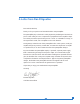
A Letter from Dan D’Agostino Dear Audio Enthusiast, Thank you for your purchase of the Krell Evolution 202 preamplifier. The preamplifier plays a vital role in audio playback by mediating the line-level output of a wide variety of source components in preparation for the amplifier’s input. At no other point in the reproduction process is music so vulnerable to change, as the signal level is small, and susceptible to noise and distortion.
SECTION ONE Evolution 202 Features and Technology This section describes the innovative features and technology of the Evolution 202 preamplifier, and defines CAST and other key terms used in this reference. The Evolution 202 Stereo Preamplifier, evolving from the flagship Evolution Two, works to carefully transmit audio signals without damaging the ephemeral staging and dimensional components of the music.
In stand-by mode, all the analog circuitry continues to operate at the same bias current; however, the main analog supply voltages decrease by 30 percent. The result is a corresponding 30 percent reduction in power consumption and heat without the need to wait for the electronics to “warm up” before listening. Revolutionary Krell CAST Technology Current Audio Signal Transmission, termed CAST, is a revolutionary method of connecting analog audio components for unparalleled sonic performance.
(SECTION ONE: Evolution 202 Features and Technology continued) Krell Current Mode maintains the integrity of the signal within the component and CAST preserves the transmitted signal between components. Together, CAST and Krell Current Mode technologies unify separate Krell components into a single global circuit. Krell Current Mode technology enjoys bandwidth increases up to an order of magnitude greater than their voltage based counterparts.
Definition of Terms The following are definitions of key terms used in this owner’s reference: Inputs and Outputs Balanced A symmetrical input or output circuit that has equal impedance from both input terminals to a common ground reference point. The industry standard for professional and sound recording installations, balanced connections have 6 dB more gain than single-ended connections and allow the use of long interconnect cables.
(SECTION ONE: Definition of Terms continued) Technology Krell Current Mode A proprietary Krell circuit topology in which the audio gain stages of a component operate in the current rather than voltage domain. This unique technology provides the component with exceptional speed, and a wide bandwidth.
TWO SECTION Unpacking and Placement This section describes the procedures for safely unpacking and placing your Evolution 202 Preamplifier. The Evolution 202 preamplifier is shipped in 1 carton consisting of 2 chassis: 1 power supply chassis and 1 preamplifier chassis. Opening the Evolution 202 Shipping Carton The Evolution 202 shipping carton measures 22.3 in. (56.6 cm) wide by 23.5 in. (59.7 cm) high by 16.2 in. (41.1 cm) deep. Preamplifier Chassis. This measures 17.3 in. (43.8 cm) wide by 3.8 in. (9.
SECTION THREE Quick Start To access the full array of available functions for the Evolution 202, please read this entire owner’s reference manual. The abbreviated routine in this Quick Start section will allow you to connect and operate the Evolution 202 quickly and enjoy its basic functions. The front and rear panels are shown in the diagrams on pages 15 and 22. Each button or feature is labeled with a callout number, and these numbers are shown in brackets in the sections below.
(SECTION THREE: Quick Start) Operating the Evolution 202 After the Evolution 202 is connected to your system and to AC power, and the front panel display has stopped scrolling, begin operation: 1. Press the power button (1) on the front panel, or the remote control power key. The standby/power LED turns blue. The display shows the factory default input: S-1, and level: -INF. The Evolution 202 is now in the operational mode. 2.
SECTION FOUR Anatomy of the Evolution 202 This section describes the Evolution 202 Preamplifier functions.
(SECTION FOUR: Anatomy of an Evolution 202 continued) Front Panel Description See Figure 1 on the previous page The Evolution 202 Preamplifier is comprised of two chassis: the preamplifier chassis and the power supply chassis. Front panel functions are described below: Chassis Preamplifier Chassis The preamplifier front panel provides power on, input and zone selection, level control, menu functions, and status display.
Preamplifier Functions 8, 9, 10 Input Select Buttons or Keys Use these buttons to select the corresponding rear panel input that is connected to a CAST (C-1, C-2), balanced (B-1, B-2), or single-ended (S-1, S-2, S-3) analog source. The front panel display shows the selected input and volume level. 11 Tape Button and LED, or Key Use this button or key to select the tape input that is connected to an analog tape source. The red tape LED illuminates when the tape input is selected.
(SECTION FOUR: Anatomy of an Evolution 202 continued) Level Control 14 Level Control Knob or Level Keys Use this knob or keys to increase or decrease system volume level or, with the balance key (C), to adjust balance. The level control knob or keys also select menu options that customize the Evolution 202. See Customizing the Evolution 202, on page 29. Navigate/Customize 5 Menu Button or Key Use this button or key to access the menu functions of the Evolution 202.
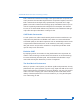
Figure 2 Evolution 202 Remote Control Power Navigate/ Customize Input Selectors 1 5 6 8 9 10 Mute Phase Level Amplifier Functions Balance CD and DVD Functions 11 12 13 14 A B C D E F G H I J Power Key Menu Key Enter Key Single-ended Input Selection Keys Balanced Input Selection Keys CAST Input Selection Keys Tape Selection Key Mute Key Phase Key Level Keys Amp Pwr Key Amp Sel Key Bal(ance) Keys Transport Keys Menu Key Direction Keys Select Key CD Key DVD Key Title Key 19 continued
(SECTION FOUR: Anatomy of an Evolution 202 continued) Remote Control Description See Figure 2 on the previous page The Evolution 202 remote provides the same power, preamplifier, level control, and navigate/customize functions as the preamplifier’s front panel. In addition, the remote has CD and DVD functions, and menu configuration functions. Keys Labled 1 to 14 These remote keys have the same function (and callout number) as the corresponding front panel controls described in the preceding pages.
Balance Functions C Bal(ance) Keys Use these with the level keys (14) to adjust the left and right channel balance. Compact Disc and DVD Functions The compact disc and DVD dual-purpose keys of the remote control are functional with all Krell compact disc and DVD players. H CD Key Use this to activate CD functions. I DVD Key Use this to activate DVD functions. D Transport Keys: Pause Key Use this key to temporarily suspend playing the current compact disc track.
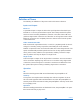
(SECTION FOUR: Anatomy of an Evolution 202 continued) Figure 3 Evolution 202 Preamplifier and Power Supply Back Panels Inputs Outputs Configurations Remote Power Phono 15 16 17 18 19 20 21 22 23 24 25 26 27 28 Balanced Inputs: B-1, B-2 Single-ended Inputs: S-1, S-2, S-3 Tape Input CAST Inputs: C-1, C-2 Tape Output Main Outputs: Single-ended Main Output Balanced Main Output CAST Outputs CAN Link In/Out RS-232 Port RC-5 In DC Power Connector 12 VDC In/Out Analog and Digital Supply Fuses IEC Power Cord
Back Panel Description See Figure 3 on the previous page The preamplifier back panel provides all input and output connections, remote control inputs and outputs, and the power connection. Back panel features and their descriptions follow. Inputs 15 Balanced Inputs: B-1, B-2 These are balanced analog source inputs with XLR connectors. 16 Single-ended Inputs: S-1, S-2, S-3 These are single-ended analog source inputs with RCA connectors.
(SECTION FOUR: Anatomy of an Evolution 202 continued) Remote Connections on the Back Panel 22 RS-232 The RS-232 port receives messages from a computer-based control system, providing integrated control of all preamplifier functions. The RS-232 input uses a 9-pin D-subminiature connector. See the Evolution 202 developer's reference, entitled RS-232 Port: Sending Commands and Interpreting Data, for more information.
Phono Stage Connector 28 Phono Power Port This port is used for connecting the preamplifier to a Krell KPE phono stage. Power 24 DC Power Connector This is used to connect the preamplifier chassis and the power supply chassis, using the provided 12-pin DC power cable. 26 Analog and Digital Power Supply Fuses Always unplug the power cord before inspecting these fuses. Always replace the fuses with the exact style and rating.
SECTION FIVE Connecting the Evolution 202 to Your System This section describes Evolution 202 Preamplifier connections. Input and Output Connections Krell recommends using its proprietary Krell CAST system for unparalleled sonic performance for connections between the Evolution 202 preamplifier and other CAST-equipped components. Krell CAST uses flexible interconnecting cables that can be drawn through tight spaces and concealed. The Evolution 202 also offers balanced operation.
Connection Steps Position the power supply and preamplifier where you intend to use them in your system. Do not move the connected chassis after they are assembled. The following steps describe how to connect an Evolution 202 preamplifier to your system: 1. Connect the power supply chassis and preamplifier chassis with the 12-pin DC cable provided, using the DC power connectors (24) on the back panels. 2. Neatly arrange and organize wiring to and from the Evolution 202 preamplifier and all components.
SECTION SIX Evolution 202 Operation The Evolution 202 Preamplifier is easy to operate. Instructions follow for on/off and stand-by operation. IMPORTANT Always mute or fully attenuate the preamplifier level when switching sources. Do not change input connections to the amplifier when the amplifier is on. Use care when setting high playback levels. Always lower the volume level at the first sign of loudspeaker distress. On/Off and Stand-by Operation When powering on any system, turn on amplifiers last.
SECTION SEVEN Customizing the Evolution 202 The Evolution 202 Preamplifier easy-to-use menu allows you to configure the following functions.
(SECTION SEVEN: Customizing the Evolution 202 continued) Menu Functions AC Mains This function enables you to operate the Evolution 202 from a switched AC outlet. If AC Mains is set to ON, the preamplifier turns on immediately, by-passing standby. Thereafter, you may switch the preamplifier to and from stand-by, using the power button or pwr key (1). The options are: OFF, ON. Enter the menu, then: 1.
Balance (channel) This function enables you to adjust the balance between the left and right output channels. The options are: CENTER, L .5-5 dB <, R .5-5 dB >. Enter the menu, then: 1. Use the level control knob on the preamplifier front panel or up and down keys (14) on the remote control to select: BALANCE. 2. Press the enter button on the preamplifier front panel or the enter key (6) on the remote control. The front panel display (3) shows the default mode: CENTER. 3.
(SECTION SEVEN: Customizing the Evolution 202 continued) Display This function enables you to turn on the front panel display (3) all the time, or turn it off after a time out. The options are: ON, TIMED. Enter the menu, then: 1. Use the level control knob on the preamplifier front panel or the up and down keys on the remote control (14) to select: DISPLAY. 2. Press the enter button on the preamplifier front panel or the enter key (6) on the remote control. The front panel display (3) reads: MODE. 3.
Info This function enables you to access information about the preamplifier software, EEPROM, and PC Boards. The PC Boards are listed in the left margin, on this page. Enter the menu, then: 1. Use the level control knob on the preamplifier front panel or up and down keys (14) on the remote control to select: INFO. 2. Press the enter button on the preamplifier front panel or the enter key (6) on the remote control. The front panel display (3) shows the software version number. 3.
(SECTION SEVEN: Customizing the Evolution 202 continued) Input Level Trim This function enables you to select an input offset for a particular input. The options are: +/-6 dB, in 1 dB increments. Enter the menu, then: 1. Use the level control knob on the preamplifier front panel or the up and down keys (14) on the remote control to select: INPUT LEVEL TRIM. 2. Press the enter button on the preamplifier front panel or the enter key (6) on the remote control.
Input Phase This function enables you to invert the absolute polarity of the selected input 180 degrees. The selections are: NORMAL, INVERT. Enter the menu, then: 1. Use the level control knob on the preamplifier front panel or the up and down keys (14) on the remote control to select: INPUT PHASE. 2. Press the enter button on the preamplifier front panel or the enter key (6) on the remote control. The front panel display (3) shows the default mode: B-1. 3.
(SECTION SEVEN: Customizing the Evolution 202 continued) (Input Trigger continued) OFF The Evolution 202 does not respond to 12 V input trigger commands. NORMAL The Evolution 202 responds to 12 V input trigger commands. THEATER The Evolution 202 responds to 12 V input trigger commands, and the theater mode enabled input is selected automatically. See Theater Mode, on page 41. IR Out Control This function enables you to access Evolution 202 IR commands and program a learning remote control.
Link Control (CAN Link) This function enables you to link and unlink CAN Link-enabled Krell products. The options are: LINKED, UNLINKED. Enter the menu, then: 1. Use the level control knob on the preamplifier front panel or the up and down keys (14) on the remote control to select: LINK CONTROL. 2. Press the enter button on the preamplifier front panel or the enter key (6) on the remote control. The front panel display (3) shows the default mode: LINKED. 3.
(SECTION SEVEN: Customizing the Evolution 202 continued) Output Trigger This function enables you to turn the two 12 Volt output triggers (25) on or off, or configure them with independent delays of up to 20 seconds. The options are: ON, OFF, DELAY. Enter the menu, then: 1. Use the level control knob on the preamplifier front panel or up and down keys (14) on the remote control to select: OUTPUT TRIGGER. 2.
RC-5 Control This function enables you to change the link transmit status of the Evolution 202. The options are: LINK TRANSMIT, LINK RECEIVE. Enter the menu, then: 1. Use the level control knob on the preamplifier front panel or up and down keys (14) on the remote control to select: RC-5 CONTROL. 2. Press the enter button on the preamplifier front panel or the enter key (6) on the remote control. The front panel display (3) shows the default mode: LINK TRANSMIT. 3.
(SECTION SEVEN: Customizing the Evolution 202 continued) RS-232 Control This function enables you to change the link transmit status of the Evolution 202. The options are LINK TRANSMIT, LINK RECEIVE. Enter the menu, then: 1. Use the level control knob on the preamplifier channel front panel or up and down keys (14) on the remote control to select: RS-232 CONTROL. 2. Press the enter button on the preamplifier channel front panel or the enter key (6) on the remote control.
Theater Mode This function enables you to select theater mode volume for a particular input. Use this function when connecting the output of a preamp/processor to the Evolution 202 for home theater applications. Configuring an input for theater mode sets that input for unity gain and suspends the level control of the Evolution 202. Volume adjustments are then made through the preamp/processor connected to the input configured for theater mode on the Evolution 202. The options are: ON, OFF.
(SECTION SEVEN: Customizing the Evolution 202 continued) Volume Display This function enables you to select the numeric mode for the volume display, displaying values from softest to loudest: 0 to 151. Alternatively, you can select the dB mode for the volume display, displaying values from softest to loudest: -inf to +12 dB. The options are: NUMERIC, dB. Enter the menu, then: 1.
SECTION EIGHT Troubleshooting System Noise When you mix and match high-performance audio components, each with its own ground potential, a low frequency hum may occur in one or both loudspeakers. If this happens when you place the Evolution 202 preamplifier into your system, follow these simple troubleshooting steps. 1. Check that all input and output connections are of sound construction. 2. With the preamplifier channel off, remove the interconnect cables, then turn the preamplifier channel on.
Warranty Krell products have a limited warranty. Amplifiers, preamplifiers, preamp/processors, and receivers carry a limited warranty of five years for parts and labor on circuitry. Loudspeakers carry a limited warranty of five years for parts and labor. CD and DVD players carry a limited warranty of five years for parts and labor on circuitry, and three years for parts and labor on mechanical parts.
If the product is serviced by a distributor who did not import the unit, there may be a charge for service, even if the product is within the warranty period. Freight to the factory is your responsibility. Return freight within the United States (U.S.A.) is included in the warranty. If you have purchased your Krell product outside the U.S.A. and wish to have it serviced at the factory, all freight and associated charges to the factory are your responsibility. Krell will pay return freight to the U.S.A.
Return Authorization Procedure If you believe there is a problem with your component, please contact your dealer, distributor, or the Krell factory to discuss the problem before you return the component for repair. To expedite service, you may wish to complete and e-mail the Service Request Form in the Service Section of our website at: http://www.krellonline.com To contact the Krell Service Department TEL 203-298-4020, Monday-Friday 9:00 AM to 5:00 PM EST FAX 203-795-2287 E-MAIL service@krellonline.
Specifications Inputs 2 pr. CAST via 4-pin bayonet connectors 2 pr. balanced via XLR connectors 3 pr. single-ended via RCA connectors Tape input 1 pr. single-ended via RCA connector Main outputs 2 pr. CAST via 4-pin bayonet connectors 1 pr. balanced via XLR connector 1 pr. single-ended via RCA connector Tape outputs 1 pr. single-ended via RCA connector, buffered Control inputs 1 RS-232 input via a 9-pin D-subminiature connector 1 remote IR detector input via a 3-conductor 3.
EVOLUTION STEREO 202 PREAMPLIFIER OWNER’S REFERENCE V06.0 KRELL 45 INDUSTRIES, CONNAIR ORANGE, TEL: CT 203-298-4000 E-MAIL: INC. ROAD 06477-3650 • FA X : USA 203-891-2028 sales@krellonline.com h t t p : / / w w w. k r e l l o n l i n e .