EVOLUTION EVOLUTION MONAURAL OWNER’S TWO PREAMPLIFIER REFERENCE
Evolution Two Monaural Preamplifier Owner’s Reference, v05.0 Krell Industries, Inc. 45 Connair Road Orange, CT 06477-3650 USA TEL 203-799-9954 FAX 203-891-2028 E-MAIL Krell@krellonline.com WEBSITE http://www.krellonline.com This product complies with the EMC directive (89/336/EEC) and the low-voltage directive (73/23/EEC). WARNINGS The Evolution Two preamplifier must be placed on a firm, level surface where it is not exposed to dripping or splashing.
Contents List of Illustrations, page iv A Letter from Dan D’Agostino, page 1 SECTION ONE: About Krell, page 3 The Krell Legacy, Revolutionary Krell CAST Technology, Ensuring Maximum Performance, Definition of Terms SECTION TWO: Unpacking and Placement, page 11 Opening the Evolution Two Shipping Carton SECTION THREE: Quick Start, page 13 Connecting the Evolution to Your System, Operating the Evolution Two SECTION FOUR: Anatomy of an Evolution Two, page 15 Front Panel Description, Remote Control Description,
List of Illustrations Figure 1, page 15 Evolution Two Preamplifier Chassis and Power Supply Chassis Front Panels Inset Evolution Two Preamplifier Channel: Front Panel View Figure 2, page 16 Evolution Two Remote Control Figure 3, page 22 Evolution Two Preamplifier Chassis and Power Supply Chassis Back Panels iv
A Letter from Dan D’Agostino Dear Audio Enthusiast, Thank you for your purchase of the Evolution Two preamplifier. My new Evolution products represent a watershed in my design philosophy and in my quest for audio components that deliver absolute truth in music reproduction. The expanse of the Evolution Two monaural design has allowed me to explore fully the advantages of current mode topologies. The resulting circuit utilizes no feedback and has a bandwidth of 2 MHz.
(A Letter from Dan D’Agostino continued) I have some exciting news for you. Work on a new source component for the Evolution Series is ongoing as of this writing. Possessed of the unique Evolution technologies that power the amplifier and preamplifier, this Evolution source will expose the real advantages of the latest recording formats while taking compact disc playback to the next level. I encourage you to audition it as soon as it is released.
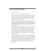
SECTION ONE About Krell This section describes the Krell Legacy, the innovative features and technology of the Evolution Two, and defines CAST and other key terms used in this reference. The Krell Legacy “I design every Krell component to set the standard for workmanship, style, and performance.” Dan D’Agostino High-end audio is a demanding pursuit—an ongoing quest for excellence in music reproduction that drives equipment manufacturers to strive for the absolute in design and performance.
(SECTION ONE: About Krell continued) Revolutionary Krell CAST Technology Current Audio Signal Transmission, termed CAST, is a revolutionary method of connecting analog audio components for unparalleled sonic performance. Innovative engineering combines the new Krell CAST circuitry with existing Krell Current Mode technology to create entire CAST systems that reproduce music with incredible range, tonality, and precision.
CAST preserves the transmitted signal between components. Together, CAST and Krell Current Mode technologies unify separate Krell components into a single global circuit. Krell Current Mode technology enjoys bandwidth increases up to an order of magnitude greater than their voltage based counterparts. This dramatic increase in circuit bandwidth delivers near perfection in the audible band that typically suffers from phase distortions in voltage circuits.
(SECTION ONE: About Krell continued) Ensuring Maximum Performance “My pursuit of excellence in sound reproduction and my love of great musical performance fuels the ongoing Evolution design effort at Krell.” Dan D’Agostino The product of breakthrough Krell technology, the Evolution Two Monaural Preamplifier works in tandem with the Evolution One Monaural Power Amplifier to provide a sound that is supremely dynamic and musical. Indeed, it is the sound of the music itself.
Fully Balanced Discrete Volume Control The volume control is realized with a 16-bit balanced resistor ladder, which uses low-resistance, high-linearity solid-state switches and discrete precision resistors. Control signals for the switches are optically coupled for low noise and maximum signal integrity. The bandwidth and transient response of the preamplifier circuitry are virtually unaffected by the volume setting.
(SECTION ONE: About Krell continued) (Separate Power Supply continued) trol circuitry team ultra-stable voltage reference chips with the same discrete highcurrent driver and output transistors used in the main analog regulators. These ample power reserves are brought to the Evolution Two via high reliability 12-pin connectors with machined, gold plated, three-amp contacts.
Definition of Terms Following are the definitions of key terms used in this owner’s reference. Configurations CAN Link The communication system that links multiple Evolution Two preamplifier channels is a sophisticated system called a controller area network (CAN). Linked Mode In linked mode, functions including power, volume, balance, phase, record, mute, and input selections are instantaneously transmitted between linked preamplifier channels.
(SECTION ONE: About Krell continued) Preamplifier Channel Also termed preamplifier or preamplifier channel. A channel is one Evolution Two, comprised of one preamplifier chassis and one power supply chassis. Right-terminated channel Any right preamplifier channel that is last in a chain of linked Evolution preamplifiers is referred to as right-terminated. There is only one RG-45 link cable connected to a right-terminated channel. Transmitter Also termed transmitter preamplifier.
SECTION TWO Unpacking and Placement This section describes the procedures for safely unpacking and placing your Evolution Two Monaural Preamplifier. Each Evolution Two preamplifier channel is shipped in 1 carton consisting of 2 chassis: 1 power supply chassis and 1 preamplifier chassis. Opening the Evolution Two Shipping Carton Each Evolution Two shipping carton measures 22.3 in. (56.6 cm) wide by 23.5 in. (59.7 cm) high by 16.2 in. (41.1 cm) deep. Preamplifier Chassis.
(SECTION TWO: Unpacking and Placement continued) (To Remove the Preamplifier from the Shipping Box continued) 2. Carefully remove the preamplifier chassis, power supply chassis, and accessories from the box. 3. Place the the preamplifier chassis and power supply chassis in a safe location and remove the protective plastic wrapping. 4. Place the power supply chassis where you intend to use the assembled preamplifier.
SECTION THREE Quick Start To access the full array of available functions for the Evolution Two Monaural Preamplifier, please read the entire owner’s reference manual. The abbreviated routine in this Quick Start section will allow you to connect and operate the Evolution Two quickly and enjoy its basic functions. Evolution Two preamplifier channels may be operated independently, or they may be operated in linked mode, using CAN Link.
(SECTION THREE: Quick Start) (Connecting the Evolution Two To Your System continued) 6. On each preamplifier channel, connect the supplied AC power cord to the IEC power cord receptacle (48). 7. On each preamplifier channel, plug the AC power cord into AC power. The front panel display (15) scrolls through EVOLUTION 2 SOFTWARE VERSION, and the red stand-by LEDs illuminate (4), indicating that the Evolution Two preamplifier is in stand-by mode.
SECTION FOUR Anatomy of an Evolution Two This section describes Evolution Two Monaural Preamplifier functions.
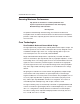
(SECTION FOUR: Anatomy of an Evolution Two continued) Figure 2 Evolution Two Remote Control 28 3 29 12 14 13 21 8 9 11 10 18 22 17 16 23 Power Preamplifier Functions Level Navigate/ Customize CD Functions Amplifier Functions 3 Power Key 8 Single-ended Input Selection Keys 9 Balanced Input Selection Keys 10 CAST Input Selection Keys 11 Tape Key 12 Mute Key 13 Record Key 14 Phase Key 21 Main Bus Key 22 Balance Key 16 Level Keys 17 Menu Key 18 Enter Key 23 Pause Key 24 Play Key 25 Stop Key 26 T
Front Panel Description See Figure 1 on page 15 Each Evolution Two Monaural Preamplifier channel is comprised of two chassis, the preamplifier chassis and the power supply chassis. Front panel functions and their descriptions follow. Chassis 1 Preamplifier Chassis The preamplifier chassis front panel provides power on, input and zone selection, level control, menu functions, and status display.
(SECTION FOUR: Anatomy of an Evolution Two continued) Preamplifier Functions 8, 9, 10 Input Select Buttons or Keys Use these buttons to select the corresponding rear panel input that is connected to a CAST (C-1, C-2, C-3), balanced (B-1, B-2, B-3), or single-ended (S-1, S-2, S-3, S-4) analog source. The front panel display shows the selected input and volume level. There is no dedicated tape input connector on the Evolution Two. B-3 and S-4 may be selected for tape input.
Level Control 16 Level Control Knob or Level Keys Use this knob or keys to increase or decrease system volume level or, with the balance key (22), to adjust balance. The level control knob or keys also select menu options that customize the Evolution Two. See Customizing the Evolution Two, on page 32. Navigate/Customize 17 Menu Button or Key Use this button or key to access the menu functions of the Evolution Two. For more information, see Customizing the Evolution Two, on page 32.
(SECTION FOUR: Anatomy of an Evolution Two continued) Remote Control Description See Figure 2 on page 16 The Evolution Two Monaural Preamplifier remote provides all of the power, preamplifier, level control, and navigate/customize functions outlined under Front Panel Description, pages 17-19. The remote control provides additional functions, including CD functions and menu configuration, accessed using only the remote control keys.
Compact Disc Functions The compact disc keys of the Evolution Two remote control are functional with all Krell compact disc players. 23 Pause Key Use this key to temporarily suspend playing the current compact disc track. Press pause again or press the play key (24), to resume playing the track at the point pause was engaged. 24 Play Key Use this key to begin compact disc playback. 25 Stop Key Use this key to end compact disc playback.
(SECTION FOUR: Anatomy of an Evolution Two continued) Figure 3 Evolution Two Preamplifier Chassis and Power Supply Chassis Back Panels 30 45 34 42 43 1 EVOLUTION TWO MAIN BUS IN IN OUT 1 INPUTS 31 33 35 36 37 OUT 2 IN POWER MAIN OUTPUTS TAPE OUTPUTS 32 LINK LINK RECORD BUS 38 39 40 41 47 44 2 EVOLUTION TWO 50/60 Hz ANALOG SUPPLY FUSE DIGITAL SUPPLY FUSE KRELL INDUSTRIES, INC.
Back Panel Description See Figure 3 on page 22 The Evolution Two Monaural Preamplifier back panel provides all input and output connections, remote control inputs and outputs, and the power connection. Back panel features and their descriptions follow. Left/Right Channel Orientation Evolution Two preamplifiers are assembled as left or right preamplifier channels. Preamplifier RCA connectors (31, 36, 38, 40) are color coded.
(SECTION FOUR: Anatomy of an Evolution Two continued) (Outputs continued) 37, 38 Record Bus Outputs The Evolution Two is equipped with one balanced record bus output with XLR connectors and one single-ended record bus output with RCA connectors. Use the record bus outputs to record a input signal other than the signal playing on the main outputs. For more information, see Play and Record, on page 30.
systems to be easily coordinated. For more information on customizing the 12 V trigger, see Input Trigger, on page 39. Mono 1/8” mini connectors are used in the following configuration: Tip = +12 V, Sleeve = GND. Notes When the Evolution Two is in the operational mode, the 12 V trigger provides 12 Volts of DC output. When the component is in the stand-by mode or off, the DC output is 0 Volts. A minimum of 30 mA is required to operate the 12 V trigger.
SECTION FIVE Connecting the Evolution Two to Your System This section describes Evolution Two Monaural Preamplifier connections and introduces the CAN Link remote control option. Input and Output Connections Krell recommends using its proprietary Krell CAST system for unparalleled sonic performance for connections between the Evolution Two preamplifier and other CAST-equipped components. Krell CAST uses flexible interconnecting cables that can be drawn through tight spaces and concealed.
The following steps describe how to connect an Evolution Two preamplifier to your system: 1. Connect each power supply chassis and preamplifier chassis with the 12-pin DC cable provided, using the DC power connectors (47) on the back panels (1-2). IMPORTANT Never connect two power supplies together. 2. In order to operate the Evolution Two preamplifier in linked mode, connect the preamplifier channels together with the supplied RJ-45 control cable.
(SECTION FIVE: Connecting the Evolution Two to Your System continued) Connections Using CAN Link The Evolution Two brings a new convenience to the operation of monaural preamplifiers, using a sophisticated, reliable control system called a controller area network (CAN). Using CAN Link, any number of preamplifier channels may be linked for multichannel playback. CAN Link enables all linked preamplifier channels to be controlled from any single linked preamplifier channel in the system.
SECTION SIX Evolution Two Operation The Evolution Two Monaural Preamplifer is easy to operate. Instructions follow for on/off and stand-by operation. IMPORTANT Always mute or fully attenuate the preamplifier level when switching sources. Do not change input connections to the amplifier when the amplifier is on. Use care when setting high playback levels. Always lower the volume level at the first sign of loudspeaker distress.
(SECTION SIX: Evolution Two Operation continued) To Turn Off Your System 1. Place the amplifiers in the stand-by mode. 2. Press the power button on the preamplifier chassis front panel or the pwr key (3) on the remote control to switch the Evolution Two to the stand-by mode. 3. Turn off the amplifiers using the back panel power switch or by disconnecting them from AC power. 4. Turn off the Evolution Two by unplugging the AC power cord from AC power.
Operation Using CAN Link When a system with linked Evolution Two preamplifier channels is powered on, left/right orientation is established immediately, with no user intervention. 1. The input selections and the power, volume, balance, phase, record, and mute adjustments you make on any preamplifier channel are instantly transmitted between all linked preamplifier channels. 2.
SECTION SEVEN Customizing the Evolution Two The Evolution Two Monaural Preamplifier easy-to-use menu allows you to configure the following functions.
Menu Functions AC Mains This function enables you to operate the Evolution Two from a switched AC outlet. If AC Mains is set to ON, the preamplifier turns on immediately, by-passing standby. Thereafter, you may switch the preamplifier to and from stand-by, using the power button or pwr key (3). The options are: OFF, ON. Enter the menu, then: 1. Use the level control knob on the preamplifier chassis front panel or up and down keys (16) on the remote control to select: AC MAINS. 2.
(SECTION SEVEN: Customizing the Evolution Two continued) Balance This function enables you to select the balance between the left and right channels. The options are: CENTER, L .5-5 dB <, R .5-5 dB >. Enter the menu, then: 1. Use the level control knob on the preamplifier chassis front panel or up and down keys (16) on the remote control to select: BALANCE. 2. Press the enter button on the preamplifier chassis front panel or the enter key (18) on the remote control.
FORCE RIGHT Use to make a right channel respond as a left channel. FORCE NONE The preamplifier channel ignores balance selections. Use this option to set up more than 2 preamplifier channels. NO OVERRIDE Return to CHANNEL ASSIGN. Serves the same function as BACK in all other menu items. For more information on linked preamplifiers, see Appendix: CAN Link and Multiple Evolution Two Preamplifiers, on page 51.
(SECTION SEVEN: Customizing the Evolution Two continued) CLONE BEGIN Sends the message that a clone is about to begin, from the clone transmitter to the clone receiver(s). CLONE TRANSMIT Once the clone begin message is sent, the clone transmitter display reads: CLONE TRANSMIT, indicating that the preamplifier is ready to transmit the clone data.
ON The front panel display is always on. TIMED The front panel display times out after 5 seconds. BRIGHTNESS Controls the brightness of the display. When the brightness setting is OFF, the display is at 50% of brightness when in menu mode, and turns completely off when you leave the menu mode. Info This function enables you to access information about the preamplifier software, EEPROM, and PC Boards. The PC Boards are listed in the left margin, on this page. Enter the menu, then: 1.
(SECTION SEVEN: Customizing the Evolution Two continued) Input Level Trim This function enables you to select an input offset for a particular input. The options are: +/-6 dB, in 1 dB increments. Enter the menu, then: 1. Use the level control knob on the preamplifier chassis front panel or the up and down keys (16) on the remote control to select: INPUT LEVEL TRIM. 2. Press the enter button on the preamplifier chassis front panel or the enter key (18) on the remote control.
Input Phase This function enables you to invert the absolute polarity of the selected input 180 degrees. The selections are: NORMAL, INVERT. Enter the menu, then: 1. Use the level control knob on the preamplifier chassis front panel or the up and down keys (16) on the remote control to select: INPUT PHASE. 2. Press the enter button on the preamplifier chassis front panel or the enter key (18) on the remote control. The front panel display (15) shows the default mode: B-1. 3.
(SECTION SEVEN: Customizing the Evolution Two continued) (Input Trigger continued) OFF The Evolution Two does not respond to 12 V input trigger commands. NORMAL The Evolution Two responds to 12 V input trigger commands. THEATER The Evolution Two responds to 12 V input trigger commands, and the theater mode enabled input is selected automatically. See Theater Mode, on page 47. IR Out Control This function enables you to access Evolution Two IR commands and program a learning remote control.
Link Control (CAN Link) This function enables you to link and unlink preamplifiers. The options are: LINKED, UNLINKED. Enter the menu, then: 1. Use the level control knob on the preamplifier chassis front panel or the up and down keys (16) on the remote control to select: LINK CONTROL. 2. Press the enter button on the preamplifier chassis front panel or the enter key (18) on the remote control. The front panel display (15) shows the default mode: LINKED. 3.
(SECTION SEVEN: Customizing the Evolution Two continued) Mute This function enables you to control the mute mode. The options are: FULL, -20 dB, BACK. Enter the menu, then: 1. Use the level control knob on the preamplifier chassis front panel or up and down keys (16) on the remote control to select: MUTE. 2. Press the enter button on the preamplifier chassis front panel or the or enter key (18) on the remote control. The front panel display (15) shows the default mode: FULL. 3.
8. Use the level control knob or up and down keys to scroll to: BACK. 9. Press the enter button or key to return to: TRIGGER 1. 10. Use the level control knob or the up and down keys to scroll to: TRIGGER 2. 11. Repeat Steps 3-7 to set Trigger 2. ON The 12 Volt trigger output is enabled at power on for the selected trigger (Trigger 1 or 2). OFF The 12 Volt trigger output is disabled at power on for the selected trigger (Trigger 1 or 2).
(SECTION SEVEN: Customizing the Evolution Two continued) Recall This function enables you to access factory default settings or your own saved settings, or to undo a clone. The options are: FACTORY, SAVED, CLONE UNDO. Enter the menu, then: 1. Use the level control knob on the preamplifier channel front panel or up and down keys (16) on the remote control to select: RECALL. 2. Press the enter button on the preamplifier channel front panel or the or enter key (18) on the remote control.
4. Press the enter button or key to confirm the selection. The front panel display reads: RS-232 CONTROL. The right-terminated preamplifier channel is the link transmitter of RS-232 data. Connect the RS-232 cable to the RS-232 connector on the right-terminated preamplifier channel. For more information on linked preamplifier channels, see Appendix: CAN Link and Multiple Evolution Two Preamplifiers, on page 51. Save This function enables you to save a copy of the current settings. The options are: GO, BACK.
(SECTION SEVEN: Customizing the Evolution Two continued) (Software Clone continued) 4. Press the enter button or the enter key (18) again. The front panel display on the clone transmitter shows the default: ARE YOU SURE NO. 5. Use the level control knob on the clone transmitter or the up and down keys to select: ARE YOU SURE YES. 6. Press the enter button on the clone transmitter. The front panel display on the clone transmitter reads: SENDING UPDATE.
Theater Mode This function enables you to select theater mode volume for a particular input. Use this function when connecting the output of a preamp/processor to the Evolution Two for home theater applications. Configuring an input for theater mode sets that input for unity gain and suspends the level control of the Evolution Two. Volume adjustments are then made through the preamp/processor connected to the input configured for theater mode on the Evolution Two. The options are: ON, OFF.
(SECTION SEVEN: Customizing the Evolution Two continued) Volume Display This function enables you to select the numeric mode for the volume display, displaying values from softest to loudest: 0 to 151. Alternatively, you can select the dB mode for the volume display, displaying values from softest to loudest: -inf to +12 dB. The options are: NUMERIC, dB. Enter the menu, then: 1.
SECTION EIGHT Questions and Answers Q. Why does the second preamplifier channel not respond when I select an input or adjust the volume on the other preamplifier channel? A. The two preamplifier channels must be linked together using the RJ-45 cable in order for functions to be sent between preamplifier channels. Q. I renamed the B-1 input on one of the preamplifier channels. Why does it still read B-1 on the other preamplifier channel? A.
(SECTION EIGHT: Questions and Answers continued) Troubleshooting System Noise When you mix and match high-performance audio components, each with its own ground potential, a low frequency hum may occur in one or both loudspeakers. If this happens when you place the Evolution Two preamplifier into your system, follow these simple troubleshooting steps. 1. Check that all input and output connections are of sound construction. 2.
Appendix: CAN Link and Multiple Evolution Two Preamplifiers The Evolution Two Monaural Preamplifier brings a new convenience to the operation of monaural preamplifiers, using a sophisticated, reliable control system called a controller area network (CAN). The CAN Link communication system enables all linked preamplifier channels to be controlled from any single linked preamplifier channel in the system. CAN Link logic distinguishes between left and right channels.
(Appendix: CAN Link and Multiple Evolution Two Preamplifiers continued) Left/Right Channel Orientation Evolution Two preamplifiers are assembled as left or right channels. Preamplifier RCA connectors (31, 36, 38, 40) are color coded. Left preamplifier channels are assembled with white RCA connectors, and right preamplifier channels are assembled with red RCA connectors. Right-Terminated Preamplifier Channel Right preamplifier channels have a unique electrical identity under CAN Link.
Warranty Each Evolution Series preamplifier has a limited warranty of five years for parts and labor on circuitry. Should this product fail to perform at any time during the warranty, Krell will repair it at no cost to the owner, except as set forth in this warranty. This warranty does not apply to damage caused by acts of God or nature.
(Warranty continued) Krell will pay return freight to the U.S.A.-based freight forwarder of your choice. Freight and other charges to ship the unit from the freight forwarder to you are also your responsibility. Krell is not responsible for any damage incurred in transit. Krell will file claims for damages as necessary for units damaged in transit to the factory. You are responsible for filing claims for shipping damages during the return shipment.
Return Authorization Procedure If you believe there is a problem with your component, please contact your dealer, distributor, or the Krell factory to discuss the problem before you return the component for repair. To expedite service, you may wish to complete and e-mail the Service Request Form in the Service Section of our website at: http://www.krellonline.com To contact the Krell Service Department TEL 203-799-9954, Monday-Friday 9:00 AM to 5:00 PM EST FAX 203-795-2287 E-MAIL service@krellonline.
Specifications Inputs 3 CAST via 4-pin bayonet connectors 3 balanced via XLR connectors 4 single-ended via RCA connectors Volume control Balanced, current-mode, 16-bit, discrete R-2R ladder Input overload CAST: 11 mA RMS Balanced: 9 V RMS Single-ended: 18 V RMS Tape input 1 balanced via XLR connector or 1 single-ended via RCA connector, user configurable Output overload CAST: 22 mA RMS Balanced: 20 V RMS Single-ended: 10 V RMS Main outputs 2 CAST via 4-pin bayonet connectors 1 balanced via XLR connector