KAV-1500 Leaderin Audio Engineering Five-ChannelPowerAmplifier Instructions for Use Owner’s Reference
KAV-1500 Five-ChannelPowerAmplifier Instructions for Use v 00.0 Krell Industries,Inc. 45 Connair Road Orange, CT 06477-3650 USA TEL 203-799-9954 FAX 203-891-2028 E-MAILkrell@krellonline.com WEBSITE http://www, krellonline.com This product complieswith the EMC directive (89/336/EEC)and the low-voltage directive (73/23/EEC). WARNINGS Theamplifier mustbe placedon a firm,/eve/surface whereit is not exposedto dt~ppingor splashing.
Contents Page INTRODUCTION 1 DEFINITION OF TERMS 1 UNPACKING 3 PLACEMENT 4 AC Power Guidelines 4 FRONTPANEL DESCRIPTION: KAV-1500 6 BACK PANEL DESCRIPTION: KAV-1500 8 CONNECTINGTHE KAV-1500 AMPLIFIER TO YOUR SYSTEM 10 Input and Output Connections 10 OPTIONAL SYSTEM CONFIGURATIONS 12 Multi AmpThroughput 12 Bridged Operation 16 Exampleof Connection Scenario: Multi PowerMode 18 AMPLIFIER OPERATION 19 On/Off and Operation 19 TROUBLESHOOTINGSYSTEM NOISE 19 QUESTIONS AND ANSWERS
Illustrations iv Page FIGURE1 The KAV-1500Front Panel 5 FIGURE 2 The KAV-1500Back Panel 7 FIGURE 3 Reconfiguring the KAV-1500for MATOperation 13 FIGURE 4 Reconfiguring the KAV-1500for Bridged Operation 15 Krell KAV-1500 Amplifier
Introduction Thankyou for your purchaseof.the Krell KAV-1500 Five-ChannelPowerAmplifier. TheKAV-1500 amplifier providessubstantial five-channeloutput powerthat delivers realistic musicreproductionat an exceptionalvalue. Theamplifier canbe customized with a variety of optional systemconfigurations,including a multi powermode usingthe Multi AmpThroughput(MAT)feature, andbridged operation. TheKAV-1500 amplifier hasbalancedandsingle-endedinputs for compatibility with other components.
Definition of Terms, continued Single-ended A two-wire input or output circuit, Usecare whenusing single-endedconnections,in whichthe ground,connectionis madelast andbrokenfirst. Turn the systemoff prior to makingor breaking single-ended connections. Single-endedconnections are not recommended for configurations requiring long cable runs. Multi-channel (DB-25) A balancedinput or output circuit that allows for the simultaneousconnectionof all audio outputs plus one 5 VDC(5 Volt tdgger) via a single cable.
Unpacking Openthe shipping box, which contains: 1 amplifier unit (packedin foamend-caps) 4 ribbon connection cables Fuses 2 AGC-~ (~-amp) speaker fuse 1 slow-blow (20 ampfor 100/120Vor 12 ampfor 220/240V)line fuse 1 12 VDCoutput (12 V trigger) cable 1 T-15 Torx wrench 1 packet containing the owner’s reference manualand the warranty registration card. IMPORTANT Twopeople are neededto removethe amplifier from the shipping box. 1.
Placement Before you integrate the KAV-1500 into your system,review the following guidelines to choosethe location for the component. This will facilitate a clean, trouble-free installation. The KAV-1500 requires at least two inches (5 cm) of clearance on each side and least two inches (5 cm) of clearance abovethe componentto provide adequate ventilation. TheKAV-1500 doesnot require any type of special rack or cabinet for installation. For the dimensionsof your amplifier see Specifications, on page23.
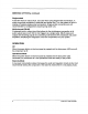
FIGURE1 THE KAV-1500 FRONT PANEL KAV-1500 1 PowerButton 2 Power LED
Front Panel Description: KAV-1500 See Figure 1 on page 5 1 Power Button Usethis button to switch the KAV-1500 powerfrom off to the operational modeand also to switch the 12 VDCoutput (12 V trigger) on andoff.
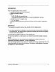
FIGURE2 3 THE KAV-1500 BACKPANEL 8 9 INPUT---~ 5 r-~ / AGC-12 / ~ 10 INPUT / 6 11 7 12 KAV-1500 PowerAmplifier ~ AGC-12 AGC42 OUTPUT (LIEF’I"SURROUNO) 20 23 19 14 19 15 21 OUTPUT (LEF’r) 1916 Balanced Inputs 3 Right Surround Input 4 Left Surround Input 5 CenterInput 6 RightInput 7 Left Input Single-endedInputs 8 RightSurround Input 9 Left Surround Input 10 CenterInput 11RightInput 12Left Input Multi-Channel Input 13 Multi-channel Input 1917 Amplifier ChannelOutputs 14 Right Surround O
BackPanel Description: KAV-1500 SeeFigure 2 on page7 TheKAV-1500 backpanelprovidesconnectionsfor all inputs andoutputs, remote connectioninput andoutput links, andACpowersupply. Balanced Inputs 3, 4, 5, 6, 7 Inputs These arethe right surround (3), left surround (4), center(5), right (6), and KAV-1500 channelinputs for output deviceswith balancedXLRconnectors.
BackPanel Description, continued Fuses 19 AGC-12 Fuses TheAGC12 Volt loudspeakerfuses protect the KAV-1500 against short circuits in loudspeakeroutput.
Connectingthe KAV-1500Amplifier to Your System INPUT AND OUTPUT CONNECTIONS Followthesesteps to connectthe KAV-1500 amplifier to your system. 1. Makesure all powersourcesandcomponents are off before connectinginputs and outputs= 2. Neatlyorganizethe wiring betweenthe amplifier andall systemcomponents. SeparateACwires from audio cables to prevent humor other unwanted noise from beingintroducedinto the system, 3. Connect the interconnectcablesfromyour outputdeviceto the amplifier inputs.
TheKAV-1500 amplifier is shippedwith shorting pins in the XLRinputs. Thesepins shouldremainin the XLRinputs if the amplifier is operatingin the single-ended mode. When the shortingpin is insert,ed, pins1 (lowerleft) and3 (top) are shortedtogether. Remove the shortingpins to connectthe amplifier for balancedoperation. TheXLRpin configurationis describedbelow: Pin1 Ground °) Pin 2 Non-inverting (0 °) Pin 3 Inverting(180 Krell recommends using balancedinterconnectcables.
Optional SystemConfigurations The KAV-1500can be reconfigured for either Multi AmpThroughput(MAT)or bridged operation. IMPORTANT Removing the cover to reconfigure for MATor for bridged operation is the ONLY instance you are authorized to removethe cover of ANYKrell component without voiding your Warranty.For moreinformation on product limitations and restrictions, see Warranty, on page 21.
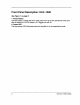
FIGURE3 RECONFIGURINGTHE KAV-1500 FOR MAT OPERATI()N PC Input Left ToSlow Start Channel 8oard J1M Board showing MAT jumper For Bridging configuration J J6fl J4N ,,,J5 J7111 J12,, J11,llJ1,II J13,1, J1811 Jr6111 CRj17 I~L~piiTB~5/~ES J~i ’ng J19~ ~J23 ~:0~i~2~ PRC- Permanent ribbon connections MAT- Multi For~,~eff.
Reconfiguring the KAV-1500for MAT See Figure 3 on page 13 Tools needed:T-15 Torx wrenchand four ribbon connection cables 1. Turn the KAV-1500 off by pressing the powerbutton (1) on the front panel. Theblue powerLED(2) extinguishes. Unplugthe ACpowercord (23) from ACpower. 2. Using the T-15 Torx wrench,removethe 14 screwsthat secure the amplifier cover. Carefully removethe cover. 3. Locatethe PCinput boardand jumperpins at the rear of the amplifier.
FIGURE4 RECONFIGURING THE KAV-1500 FOR BRIDGEDOPERATI( )N Do not attempt to bridge channels in any wayother than specified below.
BRIDGED OPERATION TheKAV-1500 canbe reconfiguredto bridge four of its amplifier channelsto operate as two combined amplifier channels.Thebridgedamplifier channelseachdeliver 1,100 Wattsinto an 8 Ohmload. Theunbridgedamplifier channelcan be connectedto a separateloudspeaker. IMPORTANT Onechannelmustremainunbridged. Reconfiguring the KAV-1500 for Bridged Operation See Figure4 on page15 Tools needed:T-15 Torx wrenchandtwo ribbon connectioncables 1.
Connectingthe Bridged KAV-1500 See Figure 2 on page 7 Connectthe bridged channelsas follows: Option1 1. Whenthe left and right channelsare bridged, connectthe output cable from the output deviceto the appropriatebalanced(7) or single-ended(12) left channelinput. 2. Connectthe positive loudspeakerlead (red) to the positive binding post on the left amplifier channel(18), Connectthe negative loudspeakerlead (black) to the positive bindingpost of the right amplifier channel(17). Option 2 1.
Multi Power Mode Connection Multi powermode is onepossibleconnection scenariousingthe KAV-1500’s Multi Amp Throughput (MAT)feature. WithMulti PowerMode,youcanusethe KAV-1500 reconfiguredfor MAT to independently power multiplepairsof stereoloudspeakers, to extendthe listeningenvironment throughout yourhome.
Amplifier Operation ON/OFF AND OPERATION Whenpoweringup your system,turn amplifiers on last. Whenpoweringdownyour system,turn amplifiersoff first. Theprocedures for amplifier operationfollow. front panel. Theblue powerLED(2) 1. Pressthe powerbutton (1) on the KAV-1500 illuminatesandyouheara click. Theamplifier is nowreadyfor operation. 2. Withthe outputdevicemutedor volumecontrol fully lowered,select an output device.Decrease or increasethe volume control to the desiredlistening level. 3.
Questions and Answers Q. ShouldI leave the KAV-1500 amplifier on at all times? A. No. Theamplifier doesnot havea stand-by mode.Leavingit on at all times would result in considerableheat output and powerconsumption.For best results, turn the amplifier off whennot in use, andallow a five minutewarm-up after it is switchedto the operational mode. See Amplifier Operation, on page 19. Q. WhenI turn the amplifier on there is a loud humthrough the loudspeakers.What should I do? A.
Warranty ThisKrell producthasa limitedwarranty =of five yearsfor partsandlaboroncircuitry. Should this product fail to performat anytimedudng thewarranty, Krell will repairit at no costto theowner, except as set forth in this warranty. Thewarrantydoesnot applyto damage causedby acts of Godor nature. Thewarranty onthis pageshall bein lieu of anyotherwarranty,expressed or implied,including,butnotlimitedto, any impliedwarranty of merchantability or fitnessfor a particular purpose.
ReturnAuthorization Procedure To return this productto Krell, please follow this procedure so that we may serve you better: 1. Obtain a Return Authorization Number (R/A number) and shipping address from the Krell Service Department. If you believe there is a problemwith your component, pleasecontact your dealer, distributor, or the Krell factory to discussthe problembefore you return the component for 2. Insureandacceptall liability for loss of repair.
Specifications KAV-1500Five-ChannelAmplifier FREQUENCY RESPONSE 20 Hz to 20 kHz +0 dB, -0.2 dB 0.4 Hz to 112 kHz +0 dB, -3 dB SIGNAL TO NOISE RATIO "A" WEIGHTED 118dB TOTAL HARMONICDISTORTION (THD) 1 kHz < 0.06% 20 kHz < 0.25% GAIN 26.4 dB INPUT IMPEDANCE 100 kOhms INPUT SENSITIVITY 2.15 Vrms OUTPUT VOLTAGE Peak to Peak RMS 166 V 59 V OUTPUT POWER, EACH CHANNEL 8 Ohms 300 W DRIVEN 4 Ohms 600 W BRIDGED 8 Ohms 1,100 W POWER CONSUMPTION Idle Max.
Krell Industries,Inc. 45 Connair Road Orange, CT 06477-3650USA TEL 203-799-9954 FAX203-891-2028 E-MAIL krell@krellonline.com WEBSITE http://www, krellonline.com KAV-1500 Five-Channel PowerAmplifier v 00.