~g and Digital Products KRELL PLAYBACK SYSTEMS KPS-20t KPS-20i KPS-20i//Integrated Integrated Transport, OWNER’S Transport Transport Processor REFERENCE & Processor & Digital Preamplifier
TABLE OF CONTENTS 2 INTRODUCTION 4 UNPACKING AND PLACEMENT 5 GENERALDESCRIPTION OF KPS-20 SERIES OWNER’SREFERENCE AC POWERGUIDELINES 6 KPS-20 SERIES FRONT AND REAR VIEW 7 KPS-20 BASIC OPERATION 8 COMPLETETRANSPORT FEATURES AND FUNCTIONS 13 KPS-20i ANDKPS-201//DETAILS 15 KPS-20i//VOLUME 16 KPS-20t DETAILS 16 TRANSPORTTO PROCESSOR INTERLINK CONSIDERATIONS 18 TIME SYNC 19 REMOTE CONTROL 22 QUESTIONS AND ANSWERS 24 KPS-20i 25 KPS-20i//TYPICAL 26 KPS-20t TYPICAL SYSTEMSETUP 27
INTRODUCTION Thank you for your purchase of the KRELL PLAYBACKSYSTEM-20 series component. Influenced by KRELL Reference and Audio Standard Series componets, the KRELL PLAYBACK SYSTEM-20’s incorporate the latest developments in Krell technology. Their advanced digital reconstruction system, input and output connection capabilities, ergonomics, and stunning aesthetics make the KRELL PLAYBACKSYSTEM-20 series an impressive statement of audio technology.
All critical circuitry utilizes four layer glass epoxy circuit boards. With its 100 VA power supply and 11 independent stages of regulation, the power supply of the KRELL PLAYBACKSYSTEM-20 is a rock solid source of pure current and voltage for the digital and Class A analog output stages. The output stage is classic KRELL. All output circuits are DC coupled, Class A and complementary. The output stage has 18 volt rails and fully differential balanced outputs on gold plated, berrylium copper XLR connectors.
UNPACKING AND PLACEMENT 1. Once the box is opened and top layer will be visible: 1 1 1 1 1 1 of foam removed, the following items KPS-20 KPS-20 Remote Control KPS-20 Custom 5 point AC power cord CD clamp (packed T-10 torx driver Packet containing the Owner’s Reference Registration Card NOTE: If any of these items are not included, dealer immediately for assistance. 2. Carefully remove the unit and accessories protective plastic wrap from the unit.
GENERAL DESCRIPTION OF KPS-20 SERIF_~ OWNER’S REFERENCE The features, functions and operation of the transport are identical for all three KPS-20 Series products. Descriptions of them are divided into two sections: Basic Operation provides a quick installation procedure; Complete Transport Features and Functions provides details on all KPS-20 transport capabilities. Features specific to the KPS-20i, KPS-20i// and KPS-20t are described on pages 13, 15 and 16 respectively.
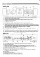
KPS-20 SERIES FaONT vii w KPS-20i/I @ 1. 2. 3. 4. 5. 6. 7. 8. 9. 10. 11. 12. 13. 14. 15. 16.
KPS-20 BASIC OPERATION Below are instructions for a quick installation of the KPS-20. Please refer to the Typical System Setup illustrations on pages 24, 25, and 26. Also, allow the unit to settle at room temperature before operation is started. 1. Plug the KPS-20 into the standard wall AC receptacle. Connect the KPS-20 output to the appropriate location: KPS-20i to preamp input; KPS-20i/I to amplifier or crossover input; KPS-20t to D/A processor input.
COMPLETE TRANSPORT FEATURES AND FUNCTIONS The KPS-20 has a wide variety of transport functions. New capabilities have been added to standard functions to enhance the use of the KPS-20, Listed below are the functions which can be accessed from the front panel and remote control. STOP: Stops the disc while playing. Erases all short Does not erase Disc Management System (DMS) data. term program memory.
0-9 NUMBEREDKEYPAD: The direct access keypad makes track selection quick and easy. When using the direct track access function, the selected track will begin play immediately after a one or two o.digit number is selected. Select the number of your choice directly or follow the program selection sequence if writing a program.. RANDOM: Will play tracks in a non-selected order. Press the Random button and the disc will begin play in a sequence other than the original.
COMPLETE TRANSPORT FEATURES How to Gain Access to a Specific 1. 2. 3. 4. FUNCTIONS - Time in a Track: Press Access. Two zeros will show on the display. Enter a one or two digit track number, then press Program. Enter a one or two digit minute number, then press Program. Enter a one or two digit second number, then press Program. The track immediately begin play at the designated time. EXAMPLE: Here is a program seconds into the piece. 1. 2. 3. 4.
2. Select the track you want first in the program. Advance and Reverse buttons to select the track number directly into the keypad. You can use the Track numbers or punch the 3. After you select the track, press the Program button selected is now in program memory. The track you NOTE: While playing the program, the Track Forward, Track Back, Repeat, Pause functions work within the program. and 4. Repeat this sequence for each track again. you want in your program.
COMPLETE TRANSPORT EXAMPLE: Here is 1. 2. 3. 4. 5. 6. 7. Press Press Press Press Press Press Press a sample Program 1 then press 3 then press 5 then press 7 then press DMS Program FEATURES DMS program - AND FUNCTIONS sequence Program Program Program Program The DMS program is now entered into the KPS-20’s permanent memory. To play the program, press DMS, then Play. The DMSprogram sequence 1, 3, 5, 7, will begin. How to PLAY a DMS Program 1. Insert the disc into the KPS-20. 2.
KPS-20i AND KPS-20i/I DETAILS This is a description of the additional features and functions commonto the KPS-20i and KPS-20i/I. Please contact your KRELLdealer or the KRELLstaff for assistance if there are any questions not covered~in this Reference. Please refer to the KPS-20i and KPS-20i/I Typical System Setups illustrations on pages 24 and 25. CAUTION: When making connections to this component or any other, make sure the power amplifier is OFF and the preamplifier is in the MUTEor STANDBY mode.
KPS-20i AND KPS-20i/1 DETAILS DIGITAL SOURCE TO KPS-20i Care should component to all industry Refer to the INTERLINK CONSIDERATIONS be taken in selecting the type of cable used to link a digital the KPS-20i or KPS-20i/I. Although the KPS-20 series will accept standard formats, we suggest using the ST wide bandwidth format. KPS-20i Typical System Setup on page 24.
KPS-20i/I VOLUME CONTROL All input and output connections for the KPS-20i/I are identical to those for the KPS-20i, with the exception that the KPS-20i/I analog outputs connect directly to the inputs of a power amplifier or crossover. Please review the KPS-20i/I Typical System Connection Diagram on page 25. Operation of the KPS-20i/I is identical to the KPS-20i with the exception of the volume control. The operation on the volume control and associated display are detailed below.
KPS-20t DETAILS All operational features and functions of the KPS-20t are described on pages 7 through 12 of the Reference. Detailed below are various issues related to the connection of the digital outputs. This information is also valid for the KPS-20i and KPS-20i/I if the optional Digital Output Module is installed. Please refer to the KPS-20t Typical System Setup on page 26 for a detailed view of how the KPS-20t is installed in an audio system.
HOW TO CONNECT ST CABLES 1. Remove the plastic cover from the outside of the ST transmitter transport) and receiver (located on processor). 2. Remove the plastic (located on cap from both ends of the ST cable. 3. Locate the key tab on the end of the ST cable. 4. Locate the slot on the top of the ST receptacle. 5. Slide the cable connector into the ST receptacle, designated slot. with the key guided into the 6.
TIME SYNC TIME SYNC Time Sync is an independent clock data transfer system that was developed to eliminate recovery jitter. Time Sync couples the high speed master clock output from the transport directly to the processor. This means there is one system master clock for the transport and processor. The use of the Time Sync system requires that a KRELLprocessor be equipped with a Time Sync input.
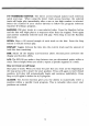
REMOTE CONTROL REMOTE CONTROL OPERATION The KPS-20 comes equipped with a universal remote control from which basic preamp, amplifier, processor, and complete transport functions can be controlled. A brief description of the buttons and their functions is provided. A diagram of the remote control is provided on page 21. All KPS-20 functions can be controlled from the front panel or the remote control. Basic preamp and amplifier functions are listed below.
REMOTE CONTROL BATTERY INSTALLATION AND REMOVAL NOTE: Batteries become intermittent. batteries. should be replaced when functions from the remote control The KPS-20 universal remote uses two AAA size 1.5 volt 1. With the T-10 torx back plate. driver remove the four screws from the remote control 2. Remove the back plate to expose the batteries. 3. Remove the old batteries and install new ones, following diagram on the plastic battery receptacle. 4.
IIIII I II I II II I I III III Ill II Amplifier meterdisplay Power\ (. \| C~,~ f-~ AMP IPOWER Amplifier power access keypad Repeat Pause~ PAUSE Stop ~~ Cover open ~ ~STO~ Track back~ Search fo~ard 0 P~Y ~ T~CK / Track forward
QUESTIONS Qo AND My CD transport should I use? ANSWERS has both fiber optic and coaxial outputs. Which one Given a choice, we prefer the ST format due to its complete isolation of the grounds between digital source and processor. This minimizes the possibility of ground loops in the digital components. The ST format also has the added benefit of substantially higher bandwidth than coaxial or the standard fiber optic interface. If a coaxial cable must be used, we suggest the AES/EBUbalanced format.
KPS-20i TYPICAL SYSTEM SETUP LOUDSPEAKERS KSA AMPLIFIER Digital components can connect to different inputs than are shown PREAMPLIFIER IR L OUTPUT KPS-20i SATELLITE RECEIVER ~-~ CABLE DIGITAL RADIO RECEIVER(DMX) 24 DAT DECK
KPS-20i/I TYPICAL SYSTEM SETUP LOUDSPEAKERS KSA AMPLIFIE & Digital components can connect to different inputs than are shown KPS-20| I I SATELLITE RECEIVER ~-~ DAT DECK CABLE DIGITAL RADIO RECEIVER(DMX) 25
KPS-20t TYPICAL SYSTEM SETUP ~"~ KSA AMPLIFIER ~~ i Different ~~~ ,[] ~ ~ ~’ R ~ k INPUT t PREAMPLIFIER ~R k OUTPUT t TIMESYNC REFERENCE KPS-20t 26 ST digital s°~tpUownt Scthan~ea~:ed
SPECIFICATIONS TRANSPORT: Modified CDM-9pro with hall effect motor, swing-arm design in a unicast frame. Custom magnetic disc clamp.
WARRANTY AND SERVICE THERE ARE NO USER-SERVICEABLE PARTS INSIDE ANY KRELL PRODUCT. KRELL PLAYBACK SYSTEM-20 has a limited and transferable warranty of five years for parts and labor and three years on trahsport related parts. The warranty period begins on the date of retail purchase,’ as noted on the retail sales slip provided by an authorized KRELLDealer or Distributor, or on the warranty registration card sent to KRELL.
The use of any packing material other than original is not recommended. KRELL may, at its discretion, pack a unit in new packing for the return shipment and bill you for such packing if the unit was packed in non-standard packing or the original packing is so damaged as to be unusable. Should you need to purchase additional packaging please contact your authorized KRELL Dealer, Distributor or KRELLfor assistance.
KRELL 45 Connair Road ¯ Orange, CT 06477 203’799-9954 ¯ Fax: 203-799-9796 Copyright 1995 KRELL P/N D960601600000