MD-20 OWNER’S REFERENCE
A. INTRODUCTION Congratulations on your purchase of the MD-20CD turntable and welcometo the KRELL family of audio components.Youhave joined a select group of listeners whoenjoy only the finest in music reproduction. Weare dedicated to the~ developmentof technologically advancedcomponentstor the reproduction o,f diglt~ly recorded music and continuing the Krell tradition ot uncompromisedperformance through leading-edge teclanology.
B. TABLE OF CONTENTS 3 UNPACKING AND ASSEMBLY 4 CUSTOM DUST COVER INSTALLATION 6 BASIC INSTALLATION AND CONNECTIONS 8 OPERATION OF THE CD TRANSPORT 10 REMOTE CONTROL 11 TRACK AND FTS PROGRAMMING 15 MAINTENANCE 16 QUESTIONS AND ANSWERS 18 SPECIFICATIONS 19 WARRANTYAND SERVICE INFORMATION C. UNPACKING AND ASSEMBLY 1. Openthe box and removethe top layer of protective foam.
D. CUSTOM DUST COVER INSTALLATION 1. Standard Version SmokedTop Cover: Removethe top cover, in its protective sleeve, from the s.hippingfoam.Toprevents.c.ra.tching, leave tlae protective sl.eeve on tlae top cover until t~lae cover mountingis complete. T.here are two pairs ot screws .with w~asher-type receptacles attachedto t-he backpanel of the unit tor mounti.ng the top cover. Centerthe hingepins on the top coverov.er toe two pairs of screws. Carefullyslide the hinges into tlae .slots formedby the washers.
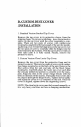
INSTALLATION OF THE CUSTOM ACRYLIC DUSTCOVER FOR MD-20 REMOVEABLE MOLDED COVER MD-20 MADE INU.S.A. NOU~ER SERVICEABLE PARTS INSIDE XLR O SPECIAL 1. To removemoldedcover, slide the cover assemblyupwarduntil the hinges are cleared from both sets of screws and washers. 2. Be sure to save all the screwsand washersafter disassembly. CUSTOM ACRYLIC COVER E PARTSINSIDE ~ ~ SPECIAL 1. Remove the four original hinge retaining screwsfromthe backof the unit. 2. Remove the three washers from each screw.
E. BASIC INSTALLATION AND CONNECTIONS 1. Place the unit on a clean, level surface awayfrom excessive heat, moist,ure or light. Ideally, the MD-20 should be placed on tlae top of an audio componentcabinet or other "openair" rigid platform. 2. TheMD-20 may.be. placed in a cabinet. It will require. 17.0 inches of vertical clearance betweenthe bottomancl top shelves for proper operation of the cover. 3. I.f space is limited, the MD-20 can be operated without its clust cover.
CAUTION: The MD-20is a CDTransport only. It is not designed to connect directly to any preampor analog signal processor. The MD-20is equipped with a special termination system called TimeSync.TimeSyncis a system that locks. the clock betweenthe MD-20 and specific Krell digitalto-analog processors. This connectionis labeled SIRE, CIALon the back of the MD-20.The termination is via an AT&T fibre op.tic cable only and is used in con.junction with any of the other digital links like the AT&T or AES/EBU.
F. OPERATIONOF THE CD TRANSPORT 1. Turn the CDtransport ONby pressing the Power b.utton. The display will illuminate. Select a disc and. p.lace it o.n the spindl_e, label side up. Put the disc staNIizer on the center of the CDso it fits securely on the drive spindle. CAUTIONS: Never operate the CDtransport without the disc stabilizer. This can result in damageto the transport or your valuable compact discs. b. Never place the disc stabilizer where the cover may accidentally close on it and damagethe cover.
3. Select a track on the CDto play with the remotecontrol or via the front panel and press the Play button. The music will nowbegin.
G. REMOTE CONTROL 1. The operating functions of the RemoteControl are describei:l below: POWER Turns unit ONor OFF STOP Stops the disc from playing PLAY Starts the disc playing at. track 1; will also restart pIay of the current track PAUSE Tem.
H. TRACK PROGRAMMING The remote control or the front panel of the MD-20can be used to programspecific tracks on a disc to be played in the order you choose. The MD-20can store up to 20 selections per program. 1. Select the track numberwhichwill start the sequence into the keypad, then push the PROGRAM or PROGR button. A "P" will appear next to the track number. 2. Enter the rest of the track selections in. yourprogramin the same manner rememberingto push the program buttonafter eachtrack selecte~t. 3.
FTS PROGRAMMING To program tracks in the FTS memory: NO.TE: Before you begin,place disc to be progra.mmed on tl~e unit and press PLAY.Oncetl~e unit reads tl~e table of contents and displays the disc’s playing time,press STOE You can now begin programming fhe FTS memory. 1. Programthe selections in the standard form described above. . After you have progra.mmedthe tracks, press the FTS ~utton on the front panel or on the remote control. The FTSindicator in the display will flash. .
TO ERASE FTS PROGRAM MEMORY NOT.E:FTS memorycan only be .erased via the front panel controls. The remote control cannot erase FTS memory. NOTE:The disc does not have to be on the MD-20to erase FTS memory. Erasure can be completed with no disc on the drive spindle. . Press the FTSbutton on the front panel. Hold the . ~u.tton in while pressingthe forward or backward track select. Youwill notice the machineis scrolling through FTS des!gnation numbers. Once you have found the FTS bdesignatlo.
I. MAINTENANCE .B. ecause of its superb build quality the MD-20 requires little maintenance.Shouldthe unit becomeexcesslvly dirty, clean the lens assemblywith a cameralens brush madeof a soft material like camelhair. Theacrylic top plate and dust cover should be cleaned with the polistiing kit provided. Readthe directions on the containers for best polishingresults. REMOTE CONTROL BATTERY INSTALLATION AND REMOVAL The batteries in the remote control should be changed whenthe tran.
J. QUESTIONS AND ANSWERS Q. MyDigital to Analog processor will accommodate eather fibre optic or coaxial digital inputs. Whichoutput should I use on the MD-20? A. Whilea high quality coaxial willperform quite well, were.commend glass fibre optic cable due to its ab.ility to completelyisolate the grouni:ling planes betweentlae transport and processor, and its resistance to RFinterference. If an AT&T or AES/EBU input is available, we recommend one of these interfaces be utilized. IQ.
Q. Dueto the exposednature of the laser assemblyis there a possibility of damagethrough laser radiation? A. No. There is an optical sensor under the CDwhenit is positioned on the transport hub. This allows the MD-20 to prohibit the laser fromturning on whenit is not covered with a CD. a~Ile own many CDsdiscs that with have the CDRings on them. AmI to use these MD-20? A. Yes, TheMD-20will accept discs with :’CDRin.gs". Dueto their very low mass, they will not damagethe MD-20’stransport.
K. SPECIFICATIONS TRANSPORT Modified Philips CDM-1MK11with Hall effect swing-arm design in a unicast frame. LASER Single Beamwith glass lens OUTPUT Digital only in industry standard SPDIFformat. 1 FIBREOPTICvia standard interface 1 COAXIALvia RCAconnector 1 AT&Tvia ST connector 1 AES/EBUvia XLRconnector REMOTE CONTROL Wireless infrared DIMENSIONS 19.0" wide, 12.5" deep 6.0" high, cover closed 15.
L. WARRANTYAND SERVICE INFORMATION There are no user-serviceable parts inside the MD-20. The MD-20has a limited warranty of three years parts and labor on transport-related parts; five years parts and labor on electronic parts. Returnfreight is includedin the warranty. Thewarranty period b.egins on t~e date of p_u_rchaseand is activated with the return ot the enclosed Warran.tyCardand a copy of the Sales receipt.
t 0 I 0 0 KRELL DIGITAL INC. 35 HIGGINS DRIVE MILFORD,CT 06460 SALES203-874-3139 FAX203-878-8373 COPYRIGHT1992 KRELLDIGITAL INC.