MD-10 OWNER’S REFERENCE
A. INTRODUCTION TCrOngratulations on yourand purchase oftothethe MD-10 CD anscription turntable welcome KRELL family oF audio components.Youha.vejoined a select groupof listeners whoenjoy only tlae tlnest in music reproduction. Weare dedicated to the~ developmentof technologically advancedcomponentstor the reproduction o.f digat~ly recorded music and continuing the Krell tradition ot uncompromisedperformance through leading-edge technology.
B. TABLE OF CONTENTS 3 UNPACKING AND ASSEMBLY 4 DUST COVER INSTALLATION 6 BASIC INSTALLATION AND CONNECTIONS 9 OPERATION OF THE CD TRANSPORT 11 REMOTE CONTROL 12 TRACK AND FTS PROGRAMMING 15 MAINTENANCE 16 QUESTIONS AND ANSWERS 18 SPECIFICATIONS 19 WARRANTYAND SERVICE INFORMATION C. UNPACKING AND ASSEMBLY 1. Openthe box and removethe top layer of protective foam.
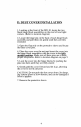
D. DUST COVER INSTALLATION 1. Lookingat the front of the MD-10,locate the two black hinge block assemblies on the rear left and right corners. (Refer to location diagram) 2. Locate the hinge pin on the back of each hinge block assembly and pull them out gently until they are fully extended. t3h. Openthe flap only on the protective sleeve and locate e three cover pins. 4. Place the cover over the unit and insert the cover into the hinge block assemblies with the cover in the ~ u~ri~ht ~osition.
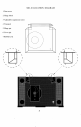
MD-10 LOCATION 1 Dust cover 2 Hinge block 3 Adjustable suspension tower 4 Transport 5 Hinge pin 6 Cover pin 7 Bubblelevel 5 DIAGRAM
E. BASIC INSTALLATION AND CONNECTIONS 1. Place the unit on a clean, level surface awayfrom excessive heat, moist.ure or light. Ideally, the MD-10 should be placed on tlae top of an audio componentcat)inet or other "openair" rigid platform. 2. TheMD-10 may.be. placed in a cabinet. It will require. 17.0 inches of vertical clearance betweenthe bottomanti top shelves for proper operation of the cover. 3. If. space is limited, the MD-10 can be operated without its clust cover.
8. Connectthe Digital Output from the MD-10to a Krell Digital Processor or other compatibledigital-to-analog audio processor. The MD-10is compatible with industry standard Fibre ~O_[?tic, Coaxial RCA,AT&T wide bandwidthFibre Optic ~1 type and AES/EBU XLRoutput connectors. NOTE: Care should be taken in selecting the type of cable used to lin.k the MD,10to your processor.
3. Connect your digital interlink between the transport , and digital-to-analog converter, if not already connectecl. 4. Select a digital source and press the TimeSyncbutton on the front of your digital-to- analo~ converter. The corresponding led will-illuminate indicating the TimeS-ync is locked. Should the TimeSync-LEDflash, tlais meansthe TimeSyncclock has not locked and. requires, resetting. Select any other digital input.on tlae digital-to-analog converter and then reselect the input, you.
F. OPERATIONOF THE CD TRANSPORT 1. Turn the CDtransport ONby pressing the Power b.utton., Thedisplay will illuminate. Select a disc an.d place it on the spindl~e,label side up. Put the disc st.alfifizer on the center ot the CDso it fits securelyon tide drive spindle. CAUTIONS: Never operate the CDtransport without the disc stabilizer. This can result in damageto the transport or your valuable compactdiscs. b. Neverplace the disc stabilizer wherethe cover may accidentally close on it and damagethe cover. c.
3. Select a track on the CDto play with the remotecontrol or via the front panel and press the Play button. The music will nowbegan.
G. REMOTE CONTROL 1. Theoperatingfunctions of the RemoteControlare describei] below: POWER Turns unit ONor OFF STOP Stops the disc from playing PLAY Starts the disc playingat. track 1; will also restart pray of the current track PAUSE Tem.
H. TRACK PROGRAMMING The remote control or the front panel of the MD-10can be used to programspecific tracks on a disc to be played in the order you choose. The MD-10can store up to 20 selections per program. 1. Select the track numberwhich will start the sequence into the keypad, then push the PROGRAM or PROGR button. A ’~" will appear next to the track number. 2. Enter the rest of the track selections in. your programin the same manner remembering, to push the program button after each track selected.
FTS PROGRAMMING To program tracks in the FTSmemory: NOTE:Before you begin,place disc to be progra.mmed on the unit and press PLAY. Oncethe unit reacls the table of contents and displays the disc’s playing_time,press STOEYou can now begin programming the FTS memory. 1. Programthe selections in the standard form described above. . After you have progra.mmed the tracks, press the FTS ~utton on the front panel or on the remotecontrol. The FTSindicator in the display will flash. b3.
TO ERASE FTS PROGRAM MEMORY NOTE:FTS memorycan only be erased via the front panel controls. The remote control cannot erase FTS memory. NOTE:The disc does not have to be on the MD-10to rase FTS memory. Erasure can be completed with no isc on the drive spindle. ~ . Press the FTS button on the front panel. Hold the . ~u.tton in while pressingthe forward or backward track select. Youwill notice t-he machineis scrolling through F.TS designation.numbers. Once you have found the FTS .designatio.
I. MAINTENANCE .B.e.cause of its superb build quality the MD-10 requires little maintenance.Shouldtlie unit becomeexcesslvly dirty, clean the lens assemblywith a cameralens brush madeof a soft material like camelhair. Theacrylic top p!ate and dust cover should be cleanedwith the poli~stiing .kit provided. Readthe directions on the containers tor best polishingresults. REMOTE CONTROL BATTERY INSTALLATION AND REMOVAL The batteries in the remote control should be changed whenthe tran.sport is no longer un.
J. OUESTIONS AND ANSWERS Q. MyDigital to Analog ~processor will accommodate either fibre optic or coaxial digital inputs. Whichoutput should I use on the MD-10? A. While a high quality coaxial willperform quite well, we re.commendglass fibre optic cabre due to its ab.ility to completely isolate the grounding planes between the. transport and processor, and its resistance to RFinterterence. If an AT&Tor AES/EBU input is available, we recommendone of these interfaces be utilized. IQ.
t~.ereDue the exposed the laser is a to possibility of nature damageof through laser assembly radiation? A. No. There is. an optical sensor under the CDwhenit is positione~l on tlae transport hub. This allows the MD-10 to p.rohibit the laser fromturning on wlaenit is not coverecl with a CD. a~Ile own many CDsdiscs that with havethe CDMD-I(~? Rings on them. AmI to use these DA.Yes, TheMD-10 will accept discs with :’CDRin.gs". ue to their very lowmass, they will not clamaget~ae MD-10’stransport.
K. SPECIFICATIONS TRANSPORT Modified Philips CDM-4 PROwith Hall effect motor, swing-arm design LASER Single Beamwith glass lens OUTPUT Digital only in industry standard SP_DIF format. 1 FIBREOPTICvia standard intertace 1 COAXIAL via RCAconnector 1 AT&Tvia ST connector 1 AES/EBUvia XLRconnector 1 SPECIALOptional TimeSync via ST connector REMOTE CONTROL Wireless infrared DIMENSIONS 19.0" wide, 12.5" deep 6.0" high, cover closed 15.
L. WARRANTYAND SERVICE INFORMATION There are no user-serviceable parts inside the MD-10. The MD-10has a limited warranty of three years parts and labor on transport-related parts; five years parts an.d labor on electronic parts, lleturn freight is includedin the warranty. Thewarrantyperiod b.egins on thee date of p_u_rchaseand is activated with the return ot the enclosed warran.ty Card and a copy of the Sales receipt.
0 0 I 0 I 0 ’ DIGITALINC. \ KRELL DIGITAL INC. 35 HIGGINS DRIVE MILFORDCT 06460 SALES203-874-3139 FAX203-878-8373 COPYRIGHT1992 KRELLDIGITAL INC.