S –1000 SURROUND PREAMP/PROCESSOR Owner’s Reference INSTRUCTIONS FOR USE
S –1000 Surround Preamp/Processor Instructions for Use v 07.0 CONTACT INFORMATION Krell Industries, Inc. 45 Connair Road Orange, CT 06477-3650 USA TEL 203-298-4000 FAX 203-891-2028 E-MAIL krell@krellonline.com WEBSITE http://www.krellonline.com IMPORTANT SAFETY INSTRUCTIONS This product complies with the EMC directive (89/336/EEC) and the low-voltage directive (73/23/EEC). 1. Read Instructions. 2. Keep these Instructions. 3. Heed all Warnings. 4. Follow all Instructions. 5.
Contents Page INTRODUCTION DEFINITION OF TERMS 2 UNPACKING 4 PLACEMENT 5 AC Power Guidelines GETTING STARTED FRONT PANEL DESCRIPTION 5 6 8 REMOTE CONTROL DESCRIPTION Battery Installation and Removal 13 13 BACK PANEL DESCRIPTION 16 CONNECTING THE S–1000 TO YOUR SYSTEM First: Connect Analog and Digital Sources Next: Connect Video Sources Last: Connect Amplifiers and Sources 19 19 20 21 OVERVIEW: SYSTEM CONFIGURATION AND NAVIGATION Configuration Steps 22 22 Navigation Conventions 23 SYSTEM C
Tables Page TABLE 1 TABLE 2 S–1000 Connections and Corresponding Factory Default Decoding Modes, by Device 14 Krell Music Surround Modes for the S–1000 62 Illustrations Page iv FIGURE 1 The S–1000 Front Panel 7 FIGURE 2 The S–1000 Remote Control 7 FIGURE 5 The S –1000 Back Panel 14 Krell S–1000
Introduction Thank you for your purchase of the Krell S–1000 Surround Preamp/ Processor. The S–1000 serves as the centerpiece in a Krell HEAT™—High End Audio Theater—system, which applies the fundamental principles of Krell engineering to the creation of a fully integrated high-performance multi-channel sound system.
Definition of Terms Following are the definitions of key terms used in your owner’s reference manual: INPUT AND OUTPUT CONNECTIONS Balanced A symmetrical input or output circuit that has equal impedance from both input terminals to a common ground reference point. The industry standard for professional and sound recording installations, balanced connections have 6 dB more gain than single-ended connections and allow the use of long interconnect cables.
Definition of Terms, continued TECHNOLOGY Krell HEAT The Krell term HEAT, or High End Audio Theater, is a design application incorporated into Krell components to enhance multi-channel home entertainment systems. A Krell HEAT system is an integrated home theater system consisting of a state-of-the-art Krell preamp/ processor and matching amplifiers that reproduce two channel and multi-channel sources with audiophile sound quality, placing the audience in the middle of a lifelike environment.
Unpacking Open the box and remove the top layer of foam. You see these items: 1 S–1000 Surround Preamp/processor 1 IEC connector (AC power) cord 1 S–1000 handheld remote control 1 CR2025 lithium battery 1 12 VDC output (12 V trigger) cable 1 packet containing the S–1000 Quick Setup Guide and the warranty registration card. Carefully remove the S–1000 and accessories from the box. Remove the foam end caps and protective plastic wrap from the component.
Placement Before you install the S–1000 Surround Preamp/processor into your system, review the following guidelines to choose the location for the component. This will facilitate a clean, trouble-free installation. The S–1000 does not require any type of special rack or cabinet for installation. For the dimensions of your S–1000 see Specifications, on pages 66-67.
Getting Started The S–1000 Surround Preamp/processor provides a variety of connection and operation options for outstanding music and cinema soundtrack reproduction, and offers a high degree of flexibility via an on-screen menu system. To setup the S–1000 quickly: IMPORTANT: ACCESSING THE ON-SCREEN DISPLAY 1. Connect the S–1000 to the rest of the components in your system, using Figure 3 on page 14 and Table 1 on page 15 as a guide. Please note: On Screen Display (OSD).
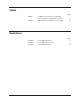
Figure 1 The S –1000 Front Panel 5 6 7 8 9 DVD CABLE SAT VCR TV 21 24 20 BALANCE CD TUNER AUX GAME TAPE/VCR2 CENTER 10 11 12 RECALL SURR/BACK PRE AMP STEREO MODE 1 MODE 2 PRO LOGIC II 17 18 POWER SAVE 21 3 SUB 4 13 27 25 14 22 23 FRONT PANEL AND REMOTE FUNCTIONS 26 BASIC OPERATION 1 Power Button/Pre Key 2 Power/Stand-by LED 3 Infrared Sensor 4 Infrared Emitter 19 11 Tuner Button/LED/Key 12 Aux Button/LED and Aux1 Key 13 Game Button/LED and Aux2 Key 14 Tape/VCR2 Button/ LE
Front Panel and Remote Control Description See Figures 1 and 2 on page 7 FUNCTIONS Button = on front panel Key = on remote control Blue LED illuminated = function active, except for power/stand-by LED which illuminates red when in stand-by mode. Basic Functions The S–1000 Surround Preamp/processor front panel and remote control access power on and off; input, and processing mode selection; monitoring and display of processor status; and balance and volume control.
Front Panel Description, continued Input Device Selection Buttons and LEDs, continued 9 TV Button/Key Press this button or key to select the television device. 10 CD Button/Key Press this button or key to select the compact disc device. 11 Tuner Button/Key Press this button or key to select the AM/FM tuner device. 12 Aux Button/Aux1 Key Press this button or key to select an auxiliary device, such as phono, tape, or an additional DVD, LD, CD, or VCR.
Front Panel Description, continued Decoding Modes, continued Note 18 Pro Logic II Button/LED/PL Key Press this button or key to select the Dolby Pro Logic II modes for Dolby Surround encoded material, including laser discs, videotapes, television broadcasts, and compact discs. The Dolby Pro Logic II modes are selected automatically if Dolby Digital source material is encoded for Pro Logic. To turn off these modes, press the Pro Logic II button.
Front Panel Description, continued Individual Channel Trim, continued 22 Surr/Back Button/LED/Rear Key Press the surr/back button or key, then use the direction or level buttons (28) to adjust the volume of the surround loudspeakers. The phrase SURROUND TRIM appears on the front panel display. To adjust the back loudspeakers, press the surr/back button again. BACK appears on the front panel display. Then use the direction or level buttons to adjust the volume of the back loudspeakers.
Remote Control Only Description See Figure 2 on page 7 BATTERY INSTALLATION AND REMOVAL The S–1000 remote control uses one CR2025 lithium battery, which is included with the shipment. To open the battery compartment on the back of the remote control: 1. Place the remote face down on the table. 2.
Front Panel Description, continued REMOTE ONLY FUNCTIONS, continued 30 Prev Key Use this key to return to the previously displayed setup menu screen. 31 Mute Key Use this key to mute the S–1000 output. When this function is active, VOLUME MUTE appears in the front panel display. 32 Enter Key Use this key to accept setup menu selections, accept an input device selection, or display current system conditions. 33 Directional Keys IN THE OPERATIONAL MODE Right Directional Key.
Figure 3 The S–1000 Back Panel 51 50 47 S-VIDEO 3 COMPONENT VIDEO 1 Pb Y Y Pr 48 56 3 1 52 55 58 POWER OUT OSD IN OSD HDMI 2 HDMI 1 HDMI 4 HDMI 3 HDMI OUT OSD 2 2 2 4 MULTI-CHANNEL INPUTS L 53 COMPOSITE VIDEO OUT Pr Pb 3 1 46 49 C SL 12VDC IN 4 2 3 12VDC OUT 1 Processor 4 ANALOG AUDIO OUTPUTS SBL SW L C R SR SBR SL L SBL C SL SBL RC-5 IN R SR SW SBR R TAPE ANALOG AUDIO INPUTS R 1 L 2 3 4 5 6 7 IN L L SR SW VCR IN OUT SBR DIGITAL
TABLE 1 S–1000 Connections and Corresponding Factory Default Decoding Modes, by Device Connect the S–1000 to the rest of the components in your system, using this table as a guide. DEVICE S–1000 CONNECTIONS FACTORY DEFAULT DECODING MODES Video Digital Audio Analog Audio Digital Dolby 2.0 DVD Component 1 COAX 1 S1 CABLE HDMITM 2 COAX 3 SAT HDMITM 1 VCR Analog Dolby 5.1 DTS 5.1 PCM Dolby D+ Dolby PLII Movie Dolby D 5.1 DTS 5.
Back Panel Description See Figure 3 on page 14 FUNCTIONS The back panel of the S–1000 Surround Preamp/processor provides all audio and video input and output connections, remote control inputs and outputs, power on and off, and power connection. The back panel functions are described below.
Back Panel Description, continued Digital Audio Inputs and Outputs, continued 44 Coaxial Digital Audio Inputs The S–1000 is equipped with four coaxial digital audio inputs with RCA connectors. Video Inputs and Outputs 45 Digital Audio Outputs The S–1000 is equipped with one digital audio outputs: coaxial with an RCA connector. 46 S-video Outputs The S–1000 is equipped with two S-video outputs with DIN connectors. The main S-video output (labeled OSD on back panel) includes on-screen display.
Back Panel Description, continued 53 HDMI™ Inputs The S–1000 is equipped with four HDMI™ video inputs. Note Back Panel Remote Control Connections The S–1000 switches HDMI™ video only. Audio signal is not available via the HDMI™ inputs. On screen display (OSD) is not available from the HDMI™ output. When an HDMI™ input is assigned to a device, and the menu key on the remote is pressed, the on screen menu is available simultaneously from composite, S-video, and component OSD outputs.
Connecting the S–1000 to Your System This section provides information about connecting the S–1000 Surround Preamp/processor to analog and digital sources, video sources, and amplifiers. The S–1000 is equipped with balanced and singleended inputs. Krell recommends using balanced interconnect cables. Balanced interconnect cables not only can minimize sonic loss but also are immune to induced noise, especially for installations using long cables.
Connecting the S–1000 to Your System, continued Next: Connect Video Sources 4. Connect the video source outputs to the appropriate video inputs on the S–1000. Component video inputs. Use the component connection when the source device (DVD) and output device (TV) both feature component connections. Component video signals use three wires that convey luminance (Y), red minus luminance [R – Y] (Pr), and blue minus luminance [B – Y] (Pb) signals.
Connecting the S–1000 to Your System, continued Last: Connect Amplifiers and Sources The S–1000 has balanced outputs with XLR connectors and singleended outputs with RCA connectors. Both outputs are active at all times, allowing simultaneous connection to separate amplifiers. Connect only one of these output formats to a single amplifier. 6. Connect the outputs of the S–1000 to the input(s) of your power amplifier(s). 7.
Overview: System Configuration and Navigation This section briefly outlines S–1000 Surround Preamp/processor configuration menus and introduces menu navigation features. CONFIGURATION STEPS IMPORTANT: FOR BEST RESULTS FOLLOW THESE STEPS The easy-to-follow, step-by-step configuration menus let you set up your S–1000 for optimum performance. Detailed instructions begin on page 24. Krell recommends that you configure your component in the sequence outlined on the main menu screen: 1.
Overview: System Configuration and Navigation, continued NAVIGATION CONVENTIONS The remote control is the main input device for configuring the S–1000. For all menu mode options, use the following keys to navigate through the configuration menu screens: 29 Menu Key Press this key once to enter the configuration menu. The front panel display reads MENU MODE. The MAIN MENU screen appears. Press this key again to exit the configuration menu. The S–1000 reverts to the operational mode.
System Configuration The S–1000 Surround Preamp/processor is shipped with factory default selections in the configuration menus. For correct operation and maximum performance, use the sequence starting below, on this page, to configure the S–1000 through the interactive on-screen menus. These menus are structured to guide you through the setup process for your loudspeakers and for each device in your surround sound system.
System Configuration, continued Step 1, Listening Room Setup STEP 1 LISTENING ROOM SETUP The first option on the main menu screen, LISTENING ROOM SETUP, lets you define the number and type of loudspeakers in your system and select the bass range for each loudspeaker. It also allows you to control the subwoofer output and set the crossover frequency. Select LISTENING ROOM SETUP, on the MAIN MENU. The SPEAKER MAIN MENU screen appears. Speaker Main Menu Screen Configure Speakers Select CONFIGURE SPEAKERS.
System Configuration, continued Step 1, Listening Room Setup continued If you have a 5.1 system, select NO BACK (loudspeakers). If you have a 6.1 system, select 1 BACK. If you have a 7.1 system, select 2 BACK. Note When 1 BACK is selected, the signal is present at the left back output. Configure Speakers, FRONT FULL RANGE Sends 20Hz to 20KHz signals to the loudspeaker. CENTER SURROUND LIMITED BACK Sends information from the crossover frequency to 20KHz to the loudspeaker.
System Configuration, continued Step 1, Listening Room Setup Speaker Distance The second option on the speaker main menu screen, SPEAKER DISTANCE, allows you to tell the S–1000 the exact location of each loudspeaker in your system. Select SPEAKER DISTANCE on the SPEAKER screen appears: MAIN MENU. The ROOM SETUP Room Setup Screen When you access the ROOM SETUP screen, the cursor is blinking at the LEFT loudspeaker.
System Configuration, continued Step 1, Listening Room Setup Calibrate Volume The third option on the speaker main menu screen, CALIBRATE VOLUME, allows you to calibrate each channel using the internal noise generator of the S–1000. Note A sound pressure level (SPL) meter is required for this procedure. Select CALIBRATE VOLUME on the MAIN MENU. The CALIBRATE ROOM SETUP screen appears: Calibrate Room Setup Screen Auto Noise Sequence Press the enter key to choose AUTO NOISE SEQUENCE.
System Configuration, continued Step 1, Listening Room Setup Set the SPL meter to C weighting and slow response. After initializing, the LEFT channel dB setting on the screen blinks, and you hear band limited white noise through the left loudspeaker. This noise continues for two seconds and then moves clockwise to the next loudspeaker in the system.
System Configuration, continued Step 2, Configure Devices IMPORTANT: PLEASE READ BEFORE STARTING STEP 2, CONFIGURE DEVICES IMPORTANT The S–1000 is shipped with pre-selected connections for each device, as well as factory default decoding modes for analog and digital inputs. See Table 1, on page 15. To illustrate the method of selecting configuration options available through the S–1000, Step 2, Configure Devices, uses one source device as an example: a DVD player.
System Configuration, continued Step 2, Configure Devices STEP 2 CONFIGURE DEVICES The second option on the main menu screen, CONFIGURE DEVICES, allows you to assign video and audio inputs to source devices and configure triggers for devices in the system. Select CONFIGURE DEVICES on the MAIN MENU. The CONFIGURE DEVICES screen appears: Configure Devices Screen Assign Video Input Select CONFIGURE VIDEO from the CONFIGURE DEVICES menu. The ASSIGN VIDEO INPUT screen appears.
System Configuration, continued Step 2, Configure Devices or DISABLED For devices that do not use a video input, for example, a CD player, there are two options: PREVIOUS or DISABLED. PREVIOUS allows the last active video input to continue to be displayed, as long as a previous selection has been made. DISABLED turns off the video outputs. Assign Video Inputs, PREVIOUS continued or PAL Choose a standard video format.
System Configuration, continued Step 2, Configure Devices Assign Analog Audio Inputs Select CONFIGURE AUDIO from the CONFIGURE DEVICES menu. The ASSIGN AUDIO INPUTS screen appears: Assign Audio Inputs Screen Select ANALOG. The ASSIGN ANALOG AUDIO INPUT screen appears. Assign Analog Audio Input Screen Use the direction and enter keys to scroll through and select the device you want to configure, select the MIGRATION/REC input, and choose the analog mode, if mode options are available.
System Configuration, continued Step 2, Configure Devices allows the S–1000 to switch to the analog input automatically, if no digital input is present. This function is particularly useful for SACD players. Assign Analog Audio Inputs, AUTO-MIGRATION ON continued The analog signal must be assigned, not DISABLED, in order for automigration to be active. Assign Digital Audio Inputs After the selections for analog audio inputs are entered, press the previous key. The ASSIGN AUDIO INPUTS screen appears.
System Configuration, continued Step 2, Configure Devices Assign Lip Synch Delay The lip synchronization screen allows you to add an adjustable amount of delay, from 0 to 200 ms, to the digital audio signal decoding process. LIP SYNC is used to synchronize a digital audio source (DVD, satellite, or cable decoder) with a display (LCD, plasma TV, or projector), when the image is delayed by video processing in the display. Select LIP SYNCH from the assign audio inputs screen. appears.
System Configuration, continued Step 2, Configure Devices Assign EQ Memory The ASSIGN EQ MEMORY screen allows you to link any one of four EQ memories, or OFF, to any one of 10 devices. Once a link is made, the selected EQ memory loads automatically every time the device is chosen. For more information on Room EQ, see pages 53-56. Select EQ MEMORY from the assign audio inputs screen. The ASSIGN EQ MEMORY screen appears.
System Configuration, continued Step 2, Configure Devices Configure Trigger The final option on the CONFIGURE DEVICES menu is CONFIGURE TRIGGER. This option allows you to customize the operation of the four remote output 12 VDC (12 Volt trigger) connectors (54) on the back panel. Select CONFIGURE TRIGGER from the CONFIGURE DEVICES menu. The CONFIGURE TRIGGER screen appears: Configure Trigger Screen Use the direction and enter keys to select the source device.
System Configuration, continued Step 2, Configure Devices Configuring Additional Inputs For each of the other devices available to your system (CABLE, SAT, VCR, TV, CD, TUNER, AUX, GAME, or TAPE/VCR2), follow the procedure outlined in Step 2, Configure Devices, pages 31-37. Configure each source device completely, before configuring the next source device. When you have configured all the devices you want the S–1000 to recognize, press the previous button (74) twice to return to the main menu.
System Configuration, continued Step 3, Configure Level Adjustment STEP 3 CONFIGURE LEVEL ADJUSTMENT Use the third option on the main menu, CONFIGURE LEVEL ADJUSTMENT to set trims, adjust modes, and set the main volume limit. Note The master volume control has a numerical range from 0 to 152. Number 31 is the Dolby reference level. The center loudspeaker, surround loudspeakers, and subwoofer volume trims have a range of +/- 15 dB.
System Configuration, continued Step 3, Configure Level Adjustment Device Trim The DEVICE TRIM is a master volume trim that is activated when an input device is selected; it has a range of +/- 15 dB. Select DEVICE TRIM from the CONFIGURE LEVELS menu. The DEVICE TRIM screen appears: Device Trim Screen Use the direction and enter keys to select the devices for which you want to set trims, and the trim level for each.
System Configuration, continued Step 3, Configure Level Adjustment IMPORTANT: PLEASE READ BEFORE CONFIGURING ANALOG INPUT TRIM An analog device must be selected in order for the analog input trim option to function. The following screen appears if an analog device is not selected: To select an analog device, first exit the menu program by pressing the menu key (29). Then press the analog device key [for example, the tape key (14 )] on the remote control. The front panel displays the device selection.
System Configuration, continued Step 3, Configure Level Adjustment Analog Input Trim Use the ANALOG INPUT TRIM menu to adjust the level of an analog input source to the S–1000. Select ANALOG INPUT TRIM from the CONFIGURE LEVELS menu. The ANALOG INPUT TRIM screen appears: Analog Input Trim Screen Use the direction keys (75) to select the anti-clip option you want (ON or OFF) and the input gain decibel level. Krell recommends leaving anti-clip ON.
System Configuration, continued Step 3, Configure Level Adjustment Music Mode Sub Trim Use the MUSIC MODE SUB TRIM menu to adjust the trim for the subwoofer, during music mode playback. The adjustment range is -10 to +10 dB. Music mode sub trim is active when using the PARTY, GENERAL ADMISSION, FRONT ROW, ON STAGE, ENHANCED STEREO, ORCHESTRA, MEZZANINE, FULL RANGE + SUB, and DTS NEO:6 modes. Select MUSIC MODE SUB TRIM from the CONFIGURE LEVELS menu.
System Configuration, continued Step 3, Configure Level Adjustment DTS Control Use the DTS CONTROL menu to adjust the signal for DTS Neo:6 music mode. The center gain adjusts the amount of center channel information present in the left and right loudspeakers. The adjustment range is 0 (no center channel information subtracted (wide sound field) to 5 (maximum level of center channel information subtracted from the left and right channels (focused sound field).
System Configuration, continued Step 3, Configure Level Adjustment PLII Control Use the PLII CONTROL menu to adjust the signal for Dolby Pro Logic II music mode, which derives a 5.0 signal from two-channel material. DIMENSION You can adjust the sound field toward the front or rear loudspeakers, to achieve a more suitable balance from all loudspeakers with certain recordings. The adjustment range is 0 (maximum surround) to 6 (center). The default setting is 3 (neutral).
System Configuration, continued Step 3, Configure Level Adjustment Maximum Volume Limit Use the MAXIMUM VOLUME LIMIT menu to set the maximum volume for your system, from 0-152. Select MAXIMUM VOLUME LIMIT from the CONFIGURE LEVELS menu. The MAXIscreen appears: MUM VOLUME LIMIT Maximum Volume Limit Screen After setting your selection, press the previous key once to return to the CONFIGURE LEVELS screen. Prev Prev When MAXIMUM VOLUME LIMIT is set, Step 3, Configure Levels Adjustment, is complete.
System Configuration, continued Step 4, Operation STEP 4 OPERATION The final option on the main menu screen, OPERATION, lets you select position and display time for on-screen display (OSD), set audio operation, program a learning remote control, adjust lip synchronization, and adjust frequency response using the Krell Digital Room Equalizer. Select OPERATION from the MAIN MENU.
System Configuration, continued Step 4, Operation The on-screen display feature allows you to customize on-screen display options. OSD Operation, continued OSD ON TIME Choose the number of seconds (0-10) that the on-screen display information remains on the screen. LINE NUMBER Choose the location (from 1, top line, to 10, bottom line) at which the on-screen display appears. Prev Audio Operation After setting your selections, press the previous key (30) once to return to the OPERATION menu.
System Configuration, continued Step 4, Operation Audio Operation, continued DOLBY MODE HOLD Dolby mode hold sets the time your S–1000 remains in Dolby Digital mode when the incoming bitstream is interrupted. Bitstreams are interrupted in some devices when you press and release fast forward, track back/forward, or change channels for a compact disc, video disc, or satellite receiver. The adjustment range is 0 (no hold) to 30 seconds.
System Configuration, continued Step 4, Operation 7.1 Input Setup The 7.1 INPUT SETUP menu allows you to select the 7.1 inputs that are connected. Select 7.1 INPUT SETUP from the OPERATION menu. The 7.1 INPUT SETUP screen appears: 7.1 Input Setup Screen ACTIVE INPUTS Use the direction keys to find the input combination that matches your connections. Press enter to set the selection. ACTIVE SW Select YES if subwoofer is present and NO if it is not.
System Configuration, continued Step 4, Operation Program Remote The PROGRAM REMOTE menu allows you to program a learning remote control to operate the S–1000. Note The infrared sensor on the front panel is inactive until programming is complete. Select PROGRAM REMOTE from the OPERATION menu.
System Configuration, continued Step 4, Operation 1. Rotate the knob (26) on the front panel to select a command. The command appears on the front panel display window (20). Program Remote, continued 2. Place the programmable remote in program mode (see the learning remote user manual). 3. Place the infrared sensor of the programmable remote so that it faces the infrared emitter (4) on the S–1000 front panel. 4.
System Configuration, continued Step 4, Operation IMPORTANT: PLEASE READ BEFORE CONFIGURING ROOM EQ SETUP The Room EQ Setup accesses the Digital Room Equalizer, a feature designed by Krell to provide every adjustment from simple bass and treble to comprehensive room correction. The Digital Room Equalizer enables you to adjust frequency response through three discrete bands (I, II, and III). The four adjustable parameters available are filter type, frequency, shape, and level.
System Configuration, continued Step 4, Operation CHANNEL SELECTION When the channel field is set to ALL, the ROOM EQ SETUP menu displays the filter settings which apply to all channels and all of the channels are filtered in the same manner. When the channel parameter selection is set to only one of the channels (L, C, R, LS, RS, LB, RB, S), the filter settings apply to each of the channels individually. IMPORTANT The selection ALL overrides individually configured channels.
System Configuration, continued Step 4, Operation Room EQ Setup The final item on the OPERATION menu, ROOM EQ SETUP, allows you to adjust your loudspeaker to your listening area using the Krell Digital Room Equalizer. Select ROOM EQ SETUP from the OPERATION menu.
System Configuration, continued Step 4, Operation Room EQ Setup TYPE continued Navigate to TYPE, and configure one, two, or all of the three bands (I, II, III) for FREQ, SHAPE, and LEVEL. Note It is not necessary to configure all three filters, you may configure only one or two filters. Not all parameters are adjustable for all filter types. APPLY Select APPLY and set the selection, if you want to hear your configuration.
Saving and Recalling Customized Settings and Restoring the Factory Default System Settings SAVING CUSTOMIZED SETTINGS To save the customized settings that you have entered, press and hold the save button (25) for approximately four seconds. The front panel displays SAVING SETUP while the settings are being stored in the nonvolatile memory of the S–1000 Surround Preamp/processor.
Operating the S–1000 ON/OFF/STAND-BY After the S–1000 Surround Preamp/Processor is connected to source devices and amplifiers, and the system setup configured, the S–1000 is ready for operation. 1. Insert the AC power cord into the IEC connector (59) on the S–1000. Insert the other end into the AC wall receptacle. 2. Move the back panel power switch (58) into the up (on) position. 3. The red stand-by LED on the front panel illuminates.
Operating the S–1000, continued Tape Input and Output, continued Notes 3. Use the tape output to create a processor loop, when the S–1000 is connected to a graphic equalizer or other ancillary equipment. Connect the equipment to the S–1000 tape outputs (34) as described in the equipment manufacturer’s manual. Press the tape button (15) or key (64) to switch between the processor output (LED illuminated) and the input source (LED not illuminated). The tape output functions only with analog sources.
Appendix: Decoding Modes for the S–1000 AUTOMATICALLY DETECTED MODES The S–1000 Surround Preamp/processor automatically engages the appropriate decoding mode for the following signals: DOLBY DIGITAL 2.0 OR DOLBY DIGITAL 2.0 + DOLBY PRO LOGIC Select a Dolby Digital 2.0 or Dolby Digital 2.0 + Dolby Pro Logic default mode using the configuration menu. All modes listed under Dolby Digital 2.0, including the default mode you have selected, can be accessed using the mode 2 button or M2 key (17).
Appendix: Additional Decoding Modes for the S–1000, continued USER SELECTABLE MODES Dolby Pro Logic II Modes User selectable modes available on the S–1000 are listed below: Dolby Pro Logic II is the next generation in Dolby Surround decoding. The Pro Logic II decoder takes 2 channels in and 5 channels out. It is designed specifically to decode all existing Dolby Surround programs with improved spatiality and directionality.
Appendix: Additional Decoding Modes for the S–1000, continued Krell Music Surround Modes TABLE 6 Krell Music Surround Modes for the S–1000 62 Krell Music Surround Modes simulate different soundfield experiences when listening to music.
Warranty To register your product for warranty benefits, please complete and return the Warranty Registration Card enclosed in the shipping box within 15 days of purchase. Thank you. Krell products have a limited warranty. Amplifiers, preamplifiers, preamp/ processors, and receivers carry a limited warranty of five years for parts and labor on circuitry. Loudspeakers carry a limited warranty of five years for parts and labor.
Warranty, continued Freight to the factory is your responsibility. Return freight within the United States (U.S.A.) is included in the warranty. If you have purchased your Krell product outside the U.S.A. and wish to have it serviced at the factory, all freight and associated charges to the factory are your responsibility. Krell will pay return freight to the U.S.A.based freight forwarder of your choice.
Return Authorization Procedure HOW TO EXPEDITE SERVICE If you believe there is a problem with your component, please contact your dealer, distributor, or the Krell factory to discuss the problem before you return the component for repair. To expedite service, you may wish to complete and e-mail the Service Request Form in the Service section of our website. ACCESSING THE SERVICE REQUEST FORM Simply click on the Service Request Form in the navigation tier on the Krell home page at http://www.krellonline.
Specifications SIGNAL-TO-NOISE RATIO "A" WEIGHTED 94 dB TOTAL HARMONIC DISTORTION (THD) UNWEIGHTED 20 Hz-20 kHz, -88 dB INPUTS ANALOG AUDIO 1 pair balanced via XLR connectors 7 pairs single-ended via RCA connectors 8 7.
Specifications, continued SURROUND ENHANCEMENT MODES KRELL MUSIC SURROUND 35 W POWER CONSUMPTION DIMENSIONS WEIGHT General Admission Front Row On Stage Enhanced Stereo Orchestra Mezzanine Full Range + Sub Monophonic Party INCHES 17.3w x 5.7h x 16.5d CENTIMETERS 43.8w x 14.4h x 41.8d SHIPPING 25 lb. 11.3 kg UNIT ONLY 19.3 lb. 8.8 kg All operational features, functions, specifications, and policies are subject to change without notification.
Krell Industries, Inc. 45 Connair Road Orange, CT 06477-3650 USA TEL 203-298-4000 FAX 203-891-2028 E-MAIL krell@krellonline.com WEBSITE http://www.krellonline.com S–1000 SURROUND PREAMP/PROCESSOR v 07.