USER GUIDE KRK MODEL V6 VIDEO SHIELDED BI-AMPLIFIED STUDIO MONITOR KRK SYSTEMS, LLC. 5452 BUSINESS DRIVE HUNTINGTON BEACH, CA. 92649 TEL: (714) 373-4600 FAX: (714) 373-0421 WEB SITE: WWW.KRKSYS.COM EMAIL: SALES@KRKSYS.
Contents Page Introduction/ Features Overview • • • • • • • • • • • • • • • • • • • • System Control • • • • • • • • • • • • • • • • • • • • • • • • • • • • • • • 2 Connecting Your System • • • • • • • • • • • • • • • • • • • • • • • • • • 2~3 Installing and Positioning Your Monitors • • • • • • • • • • • • • • • 3~5 Design Goals and System Highlights • • • • • • • • • • • • • • • • • • Troubleshooting • • • • • • • • • • • • • • • • • • • • • • • • • • • • • • • 7~8 Specifications • • • • • • • • • • • •
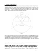
System Control INPUT SENSITIVITY Input sensitivity is adjusted (counterclockwise reduces sensitivity) by the SYSTEM GAIN control found on the rear panel. Adjustment range is from -30dB to +6dB. Factory preset gain is +6dB, which should suffice for most conditions. Normally adjustments would be made if you’re using your V6 in a surround system and you need to balance levels or if your monitor send is too hot and not adjustable.
If the fuses blow immediately upon power up, this indicates a fault condition and the monitor should be returned to KRK for repair. NEUTRIK® COMBO CONNECTOR The Neutrik® Combo connector accommodates ¼” phone plugs, XLR, TRS. Please note that PIN 2 is hot! If you are using an unbalanced connection make sure and wire PIN 1 and PIN 3 together at the source end. Installing Your Monitors The close-field monitor, by definition, reduces room interaction.
Figure 1 Mid-Field Configuration – This configuration is basically the same as the Close-Field set-up. (see Figure 2) It is normally used with larger monitors or when the monitors are too large or heavy for the meter bridge. This set-up has the potential for a larger sweet spot and better spatial imaging. Make sure that the height of the woofer is above height of the console. Figure 2 SUBWOOFER SET-UP Begin by determining the best location for your subwoofer.
Figure 3 5
5.1 CHANNEL SURROUND SET-UP Begin set-up by placing the Left and Right front channels 30º degrees from the Center channel and equidistant to the listening position (Figure 4). The Left Surround (Rear) and Right Surround (Rear) channels should be placed 110º degrees from the Center channel. Their location should also be equidistant from the listening position. The subwoofer (Low Frequency Effects) channel is most effective when situated directly below the Center channel (as shown in Figure 4).
when transporting or shipping your V6.
Design Goals KRK’s design goal for your V6 was to create a monitor capable of accurately reproducing sound with unsurpassed clarity and accuracy. Other monitors in the marketplace tend to modify, extend, or “tilt” their response above 1 kHz to sound more “spatial, exciting and impressive”. What is often overlooked is this practice tends to make you incorrectly balance your mixes to compensate for this effect, leading to poor “translation”.
Troubleshooting Problem: If there is no power, check to see if... • • • • The power cord is plugged into both the IEC socket on the rear panel of the unit and into the AC mains The AC mains voltage is matched to the operating voltage requirements (See Changing Voltage in the Connecting the System section on page 3). If the AC mains voltage is higher than the V-8’s selected voltage it is possible that the fuse needs to be replaced. (See Changing Fuses in the Connecting the System section on page 3).
• • • Play some non-distorted source material at a low volume. Carefully cover the tweeter (to block the sound) without touching the diaphragm. Is the woofer producing a clean sound? If there is not a clear tonal quality or any sound at all then the woofer probably needs to be replaced. Cover the woofer so you can hear mostly the tweeter. Is the tweeter producing a clear sound? If there is not a clear tonal quality or any sound at all then the tweeter probably needs to be replaced.
11
Specifications THE V6 POWERED STUDIO MONITOR Frequency Response High Frequency Driver Low Frequency Driver Cabinet 58Hz -22kHz ±2dB Shielded 1” (25mm) Silk Soft Dome Shielded 6” (203.2mm) Polyvinyl 13.4 liter bass reflex and ¾” MDF construction, Neutral Gray Zolatone ® Finish Dimensions Net Weight 9” W x 13-1/16” H x 12” D (279mm W x 406mm H x 304.8mm D) 38 lbs. ea. (17.27 kg) THE V6 AMPLIFIER Power Rating Signal to Noise T.H.
KRKandV6areregisteredtrademarksofKRKSystems,Inc.
Safety Instructions: English This symbol is intended to alert the user of important operating and maintenance (servicing) instructions in the literature provided with the equipment. This symbol is intended to alert the user of the presence of un-insulated “dangerous voltage” within the products enclosure that may present a risk of electric shock. Caution: To prevent the risk of shock, do not remove the cover (or open the speaker enclosure). There are no user serviceable parts inside.
Explanation of graphical symbols The lightning flash with arrowhead symbol, within an equilateral triangle, is intended to alert the user to the presence of uninsulated “dangerous voltage” within the product’s enclosure that may be of sufficient magnitude to constitute a risk of electric shock to humans.
Consignes de Securite: Francais Ce symbole sert à avertir l’utilisateur que la documentation fournie avec le matérial contient des instructions importantes concernant l’exploitation et la maintenance (rèparation) Ce symbole sert à avertir l’utilisateur de la présence dans le boìtier de l’appareil de “tensions dangereuses” non isolées posant des resques d’électrocution. Attention: Afin d’éviter tout danger d’électrocution, ne pas enlever le couvercle(ni ouvrir le boitier).
Explication des symboles graphiques Le symbole “éclair” avec fléche à l’intérieur d’un triangle équilatéral est utilisé pour alerter l’utilisateur de la presence à l’intérieur du coffret de “voltage dangereux” non isolé d’ampleur suffisante pour constituer un risque d’elétrocution.