
User Manual


6 Installation and operating instructions BM 702 (07/00)
c) Purging device
Remove screw plug ¼" R and screw in
screwed tube joint, e.g. Ermeto ¼" R.
Consult “Ex“ specifications relating to the
purging circuit (provided by customer)!
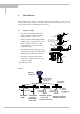
Installation on the tank
• Do not forget the gasket when
positioning the BM
702 on the tank
nozzle flange. Align BM 702 and gasket,
slightly tighten nuts on stud bolts (by
hand).
• Press shielding strip C* in the gap
between tank and BM
702 flanges and
secure with strap retainer S* (both
items included with supply).
• Strap retainer S* must fit closely and
overlap both flanges.
* only required for European radio approvals
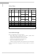
• Tighten down stud bolt nuts firmly. The
tightening torque is dependent upon
the strength properties of the stud
bolts and the pressure rating of the
tank
C* = shielding strip B = BM 702 flange
S* = strap retainer F = tank flange
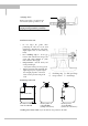
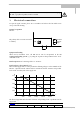
Positioning on the tank
D
>1/7×H, but max. 1/3×D
H
Recommended distance Do not position in Do not position
from the tank wall tank centerline! above internals!
(multiple reflections!) (interference reflections!)
A Stilling well or Wave-Guide may be mounted in any position on the tank!