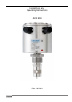
Installation and Operating Instructions ACM 500 Date: 1.02.
Contents Items supplied.................................................................................................................................... 3 System description ............................................................................................................................ 3 Product liability and warranty ............................................................................................................. 3 CE / EMC / Standards / Approvals.................................
Items supplied • • • Measuring instrument Hygienic adapter Installation and operating instructions System description Inputting physical quantities into an SPC or PLC control or other computer and control systems requires accurate and reliably working sensors. The sensor is a detecting element that converts physical quantities, such as temperature, level, pressure, conductivity, turbidity and flow, into an electrical signal.
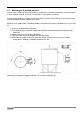
1 Installation 1.1 Mechanical installation Use only the recommended sleeves or adapters. When installed with foreign adapters, no guarantee can be given for proper functioning or leak-tightness. Do not use Teflon or paper gaskets. When installing in pipes, it is advisable to align the bore at the sensor in the direction of flow. This will ensure good exchange of the medium and good cleanability. The display unit is then positioned at right angles to the pipe.
1.3 Mounting of 3A marked products The 3A mark is valid only when the product is mounted in a 3A marked counterpart and installed acc. to the installation manual. Use also a 3A marked O-ring or gasket if relevant. The 3A marked products conforms to the 3A sanitary standards criteria. Materials and surfaces fulfil the FDA demands and are certified by EHEDG. EPDM O-rings supplied with 3A marked products are conform to sanitary standards class II (8% milk fat).
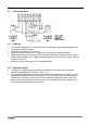
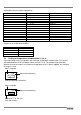
2 Electrical connection Terminals 1(+) and 2(-) are used for supplying a DC voltage of 18...36V. Terminal 2 is connected to the housing via a protective diode. The maximum power consumption is 180 mA. This value should be taken into account for the recommended fuse. An active 4...20 mA current output, galvanically isolated from the supply voltage, is available at each of terminals 3 and 4, and 5 and 6. Terminal pair 3/4 supplies the conductivity signal, terminal pair 5/6 the temperature value.
2.1 2.2 • • • • • 2.3 • • Connection plan: Start-up Check that the display unit is correctly aligned; it should where possible be perpendicular to the direction of flow (for pipes). Check the leak-tightness at the sleeve. Make sure that the cable glands are tight and the M12 plugs are properly bolted. Without selection of the measuring range and without parameter assignment by user, the device after connection to the supply voltage will operate in the measuring range 0...200 mS, 0...150°C und 2%/K.
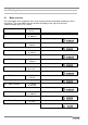
3 Setting the parameters 3.1 Menu structure For a description of the respective menu screens please follow the two-digit numbering in these Instructions. The second digit indicates whether the display menu (x0) or the relevant submenu/setting menu (x1) is meant. 00 Display 1 10 20 30 40 50 60 70 80 90 8 Meas. Range 1 TC 1 Meas. Range 2 TC 2 Meas. Range 3 TC 3 Meas. Range 4 TC 4 Temp. Range 1 1 2 2 3 3 4 4 117.9 ms 25.4 °C 01 Software version V 1.00 11 Meas.
3.2 Measured data/version indication 0 Standard indication of conductivity and temperature. If no input is made, automatic return to measured data indication after 60 seconds. The bottom left digit indicates the measuring range 1…4 that has been selected via control inputs R2 and R1. Measured conductivity 117.9 ms 25.4 °C 1 00 Measured temperature External meas. Range option 1....4 V 1.00 01 Software version Submenu 01 indicates the implemented software version. 3.
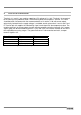
Adjustable measuring ranges conductivity: No. 1 2 3 4 5 6 7 8 9 10 11 12 13 14 Range 0... 0.5 ms 0... 1 ms 0... 2 ms 0... 3 ms 0... 5 ms 0... 10 ms 0.. . 20 ms 0... 30 ms 0... 50 ms 0...100 ms 0...200 ms 0...300 ms 0...500 ms 0...999 ms Resolution 0.001 ms 0.001 ms 0.010 ms 0.010 ms 0.010 ms 00.10 ms 00.10 ms 00.10 ms 00.10 ms 000.1 ms 000.1 ms 000.1 ms 000.1 ms 000.1 ms Ranges set in as-delivered condition: Meas. range 1 2 3 4 3.4 mS 0...200 0...20 0...2 0...0.
Directions for setting the temperature compensation: • The actual conductivity measured is indicated in the setting menu. This allows easy laboratory determination of the temperature coefficient (TC) of a liquid: Dip the device measuring head in the sample liquid (making sure there are no gas bubbles in the channel bore). Heat the sample to exactly 25.0°C, if possible. Note down the indicated conductivity (ensure adequate modulation, adjust measuring range if necessary).
4 Maintenance / Error handling 4.1 Error displays The measuring device is self-monitoring for errors and plausibility. The indication in the display supplies information about possible error conditions. The current outputs, too, are controlled in the event of an error. 4.1.1 Overranging of the conductivity measuring range Up to 21.6 mA, the current output follows linearly to the measured value (overrange).
4.1.4 Overranging of the ADC for temperature Independent of the measuring range setting for temperature, this is always measured in the – 20...150°C range. Outside these limits the device will go into error condition. Since conductivity can no longer be compensated, the current output for conductivity will also indicate the error condition with 2.4 mA. The current value for temperature will, depending on whether under- or overranging has occurred, go to 2.4 mA and 21.6 mA, resp.
6 Technical data extract Temperature range Operating pressure Inputs Outputs Repeatability, cond. Accuracy, temp. Response time, temp. Voltage supply 6.1 14 –20...+130 °C, 140 °C < 60 min. max. 10 bar 2 x 24-V control input (pnp); 18 V ... 36 V 2 x 4...20 mA active galv. sep.; load max. 500 Ohm < ±1% of full-scale range < ±0.2 °C (0...50 °C), ≤ ±0.5 °C (-20...150 °C) T 90 < 4.5 s 18...36 V DC; 180 mA max.
7 Type code 7.1 Ordering code Ordering code Length of measuring head from edge of sleeve 37 mm Electrical connection 0 Cable gland M16 4 Plug M12 Length of measuring head from edge of sleeve 84 mm Electrical connection 4 Cable gland M16 6 Plug M12 V GP0 10004 7.2 Spare parts Should a replaceable part of the probe be lost or damaged, replacements can be ordered on the basis of the part number. Designation Housing lid Cable gland M16 Connector inlet connector 7.3 Type KMD.016.090.010 KVV.M16.010.
8 Product description 8.1 Range of application The compact inductive conductivity sensor allows determination of the electrical conductivity of liquids. The small size of the measuring head allows installation in pipes sized DN40 and higher. The high-sensitivity resolution of 1 µS/cm together with a fast response time ensures reliable detection of media even with only minor differences in conductivity (e.g. beer – beer). 8.
8.
9 18 Notes ACM 500 02/2013
If you need to return a device for testing or repair to KROHNE Your instrument has been carefully manufactured and tested. If installed and operated in accordance with these operating instructions, it will rarely present any problems.