© KROHNE 12/2002 7.30920.32.
Warning! • No safety technical changes may be made to the devices. Unauthorized changes might affect the explosion safety of the devices. • These additional instructions are an extension to the Installation and Operating Instructions and only applies for the EEx version of the IFM 4042 K magnetic-inductive compact flowmeter.
1 System components 1.1 General information General information The Altoflux 2W IFM 4042 K-EEx electromagnetic compact flowmeter in 2wire technology is in accordance with European Directive 94/9/EC (ATEX 100a) and approved for hazardous classified locations of Zone 1 and 2 under: KEMA 01 ATEX 2200 X The IFM 4042 K-EEx compact flowmeter is designed for ambient temperatures in the range of -40°C up to +60°C. The allowed process liquid temperature is a.o.
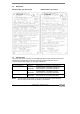
1.2 Data plates IFM 4042 K-EEx, type "EEx de [ib]" 1.3 IFM 4042 K-EEx, type "EEx de" Primary head The primary head is the measuring unit of the IFM 4042 K-EEx compact flowmeter and contains two field coils (see table below for the type of protection) and two electrodes in type of protection intrinsic safety category "ib" according to EN 50020.
1.4 IFC 040-EEx signal converter The IFC 040-EEx signal converter consists of a cylindrical housing of die-casted aluminum, which has two separate compartments, divided from each other by an integrated wall with casted flameproof terminal feed-through. The neck at the bottom of the housing contains a flameproof cable feed-through. The signal converter housing is on both ends closed by a cylindrical threaded cover with O-ring sealing.
2 Electrical connection 2.1 Equipotential bonding system The IFM 4042 K-EEx magnetic-inductive compact flowmeter must be incorporated into the equipotential bonding system through the internal of external PE-clamp. Latter clamp is suitable for wires till 4 mm2 cross section. Disconnection from the equipotential bonding system is only allowed when the flowmeter is not in contact with power supplies or ground voltages outside the hazardous area. 2.
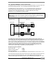
Version A Terminal compartment "EEx de [ib]" with Um = 60 V The customer can decide in which type of explosion protection the output circuits - current output, additional power supply and binary outputs (i.e. pulse and/or status outputs) - can be driven: in type of protection "EEx ib", "EEx e" or "EEx d". If type of protection EEx e or EEx d is used, the markings for "Intrinsically safe" - that are blue oring around the cable gland and the blue sticker in the connection compartment - should be removed.
2.
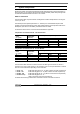
2.5 Safety-technical data Important The functional-technical data must also be regarded, therefore see the standard installation and operating instructions. Safety-technical data of output circuits Terminal Function Electrical data (per circuit) designation Type of protection "EEx ib" Type of protection "EEx e" Circuit 1 = 14 - 36 Vdc Current output, passive Un = 4 - 20 mA In (2-wire connection) I, I ⊥ Maximum values: Um = 250 V 4 - 20 mA, HART = Ui = 30 V, Ii = 100 mA, possible Pi = 1.
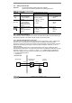
2.6.2 Example of IFM 4042 K in 2×2-wire mode (4-wire) The diagram shows an example of the connection of the IFM 4042 K-EEx in 2x2-wire mode. As in the previous example (see Sect. 2.6.1), the terminal compartment is again version A. The additional power supply (terminals 1L=, 0L=) of the IFM 4042 K-EEx is supplied by an external power supply unit through an "EEx i" zener barrier with a linear output load.
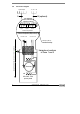
3 Operation of the signal converter The IFM 4042 K-EEx contains the IFC 040-EEx signal converter electronics unit, which is equipped with a display unit that contains magnetic Hall sensors. These Hall sensors enable the settings of the IFC 040-EEx electronics unit to be set respectively reset with the help of the with the apparatus delivered bar magnet without opening the flameproof signal converter housing in the hazardous area.
7 Replacement of electronic unit Important! The following instructions must be followed carefully, when the IFC 040-EEx signal converter housing has to be opened respectively closed again ! Before opening • Make absolutely sure that there is no explosion hazard! • If necessary provide a "Gas-free certificate"! • Make sure that all connecting cables are safely isolated from the power supply! When the instructions above are strictly followed, the display cover (with the glass window) can be removed. 7.
8 EC Declaration of conformity ALTOFLUX 2W IFM 4042 K - EEx 13
9 14 EC-Type examination certificate ALTOFLUX 2W IFM 4042 K - EEx
ALTOFLUX 2W IFM 4042 K - EEx 15
ALTOFLUX 2W IFM 4042 K - EEx
ALTOFLUX 2W IFM 4042 K - EEx 17
ALTOFLUX 2W IFM 4042 K - EEx
ALTOFLUX 2W IFM 4042 K - EEx 19
ALTOFLUX 2W IFM 4042 K - EEx
ALTOFLUX 2W IFM 4042 K - EEx 21