© KROHNE 02/2001 DIN A4: 7.10004.31.00 US size: 7.10004.71.00 GR/OP Installation and operating instructions ALTOFLUX 2W IFM 4042 K Electromagnetic flowmeters Applicable to Software Versions ● Display/Control unit No. 3.19019.xx00 ● ADC module No. 3.19749.xx00 ● I/O module No. 3.18748.xx00 How to use these Instructions The flowmeters are supplied ready for operation.
&RQWHQWV • • • • • Your operatig data System description Product liability and warranty CE / EMC / Standards / Approvals Software history 7HLO $ ,QVWDOODWLRQ DQG 6WDUW XS 1 1.1 1.2 1.3 1.4 1,5 1.6 1.7 Installation Items included with supply Handling Installation location Suggestions for installation Installation in the pipeline Torques Grounding 2 2.1 2.2 2.3 Electrical connection Information on electrical connection and connection data Output circuit diagrams Characteristic of the outputs 3 3.1 3.
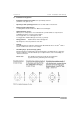
6\VWHP GHVFULSWLRQ ystem description Electromagnetic 2-wire flowmeters with IFC 040 signal converter are precision instruments designed for linear flow measurement of liquid products. The process liquids need to be electrically conductive, ≥ 5 µS/cm (for cold demineralized water ≥ 20 µS/cm). Depending on the meter size, the full-scale range Q100% can be set between 85 Liter/h and 763 m3/h, equivalent to a flow velocity v = 0,3- 12 m/s, see flow table in Section 5.1.
Part A Installation and Start-up Section 1.1 + 1.2 ,QVWDOODWLRQ 1.1 Items included with supply • • • • • Flowmeter in the size as ordered Connecting wires for grounding, refer to Section 1.7 Grounding Certificate of calibration data Grounding rings (option), if ordered Installation and operating instructions for the signal converter Fitting accessories (stud bolts, screws, gaskets, etc.) are not supplied, to be provided by customer! 1.
Section 1.3 Part A Installation and Start-up 1.3 Installation location • Temperatures Refer to Section 5.6 “Limits“ for operating pressure and vacuum load based on flange standards and type of tube liner.
Part A Installation and Start-up Section 1.4 1.
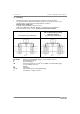
Section 1.5 Part A Installation and Start-up 1.5 Installation in the pipeline • Installation material not included, to be provided by customer (stud bolts, nuts, gaskets, etc.). • Pipe flanges and operating pressure: refer to “limits“ tables in Section 5.6 • Distance between pipe flanges: see fitting dimension a in Section 5.
Part A Installation and Start-up Section 1.6 1.6 Torques • Stud bolts: tighten uniformly in diagonally opposite sequence. See table for number and type. • 10 Nm ~ 1.0 kpm ~ 7.23 ft × lbf Meter size DN mm 10 15 25 50 80 100 150 Pressure rating PN 40 40 40 40 25 16 16 02/2001 Bolts 4 × M 12 4 × M 12 4 × M 12 4 × M 16 8 × M 16 8 × M 16 8 × M 20 Max. torques Nm ft × lbf 7.6 9.3 22 55 47 39 68 5.5 6.
Section 1.7 Part A Installation and Start-up 1.7 Grounding • • • • All flowmeters must be properly grounded to avoid personnel shock hazard. The ground conductor should not transmit any interference voltages, therefore do not ground any other electrical devices together with this conductor. Repeater power supply unit Protective separation (PELV) must be ensured (VDE 0100 / VDE 0106 or IEC 364 / IEC 536, or equivalent national regulations).
Part A Installation and Start-up Section 2.1 (OHFWULFDO FRQQHFWLRQ 2.1 Information on electrical connection and connection data • Rated values: The flowmeter housings protect the electronic equipment from dust and moisture and should always be kept properly closed. Creepage distances and clearances in air have been dimensioned in conformity with VDE 0110 and IEC 664 for contamination category 2.
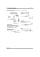
Section 2.2 Part A Installation and Start-up 2.2 Output circuit diagrams Supply power and current output - standard Note data given in Sect. 2.1! Supply power and current output - operation via repeater power supply unit Repeater power supply unit Repeater power supply unit, e.g.: CEAG 6 / 420 or Phoenix Contact PI/Ex-ME-RPSS-I/I 12 Note data given in Sect. 2.
Part A Installation and Start-up Section 2.2 Pulse or status output current limited to 100 mA Note data given in Sect. 2.1! Pulse or status output - operation via repeater power supply unit Repeater power supply unit Repeater power supply unit e.g.: Phoenix PI/Ex-ME-2NAM/COC 02/2001 Note data given in Sect. 2.
Section 2.3 Part A Installation and Start-up 2.3 Characteristic of the outputs Fig. 1 Low-flow cutoff SMU (see Fct. 1.3 in Section 4.4) I,P,S,.. -1.Number -2.Number L. F. Cutoff Q 2.Number 1.Number Fig. 2 Current output (see Fct. 1.5 in Section 4.
Part A Installation and Start-up Fig. 3 Section 2.3 Pulse output (see Fct. 1.6 in Section 4.4) I,P positive direction I,P absolute I 100% I100% I0% I0% Q 0 -Q100% Q100% Q 0 Q100% I,P negative direction I100% I0% Q -Q100% Fig. 4 0 Status output: Automatic range change BA (see Fct. 1.7 in Section 4.
Section 2.3 Fig. 5 Part A Installation and Start-up Status output: Limit switches (see Fct. 1.7 in Section 4.4) S S closed closed open open Q on limit off limit -off limit -on limit off limit on limit -on limit -off limit Fig. 6 Q Noise / Change of flow (see Fct. 3.4 in Section 4.4) Noise without Noise Filter g Chan Flow e Noise Level Noise Noise Q -Noise Flow Fig. 7 0 Noise Flow Pulse duration (see Fct. 3.4 in Section 4.
Part A Installation and Start-up Section 3.1+ 3.2 6WDUW XS 3.1 Power ON and measurement • Before powering the system, please check that it has been correctly installed according to Sections 1 and 2. The flowmeter is delivered ready for operational use. All operating data have been factoryset in accordance with your specifications. Please also refer to Section 3.2 “Factory settings”. Power the unit, and the flowmeter will immediately start process flow measurements.
Section 4.1 Part B IFC 040 Signal converter 2SHUDWLRQ RI WKH VLJQDO FRQYHUWHU 4.1 KROHNE operator control concept 136.49 Measuring mode m3/h → ↵ Menu column 4.0 Function column RESET 4.2 COUNTER RESET 4.1 ERROR RESET Data column 3.6 HART 3.5 HARDWARE 3.4 APPLICATION 3.3 ZERO SET 3.2 FLOW METER 3.0 INSTALLATION 3.1 LANGUAGE 2.2 HARDWARE INFO 2.0 TEST 2.1 TEST Q 1.7 STATUS OUTPUT 1.6 PULSE OUTPUT 1.5 CURRENT OUTPUT 1.4 DISPLAY 1.3 L.F.CUTOFF 1.2 TIME CONSTANT 1.
Part B IFC 040 Signal converter Section 4.2 4.2 Operating and check elements Control by way of ... 5 IFC040 090 D IFC 6 1 . m3/h 2 3 Flow rate + Totalizer ... the 3 keys , after twisting off the cover of the electronics compartment using the special wrench (supplied). ... the 3 magnetic sensors and the bar magnet (supplied) without opening the housing.
Section 4.3 Part B IFC 040 Signal converter 4.3 Function of keys The cursor, flashing part of display or horizontal scrolling, has a grey background. To start operator control Measuring mode Operator control mode 1 3. 5 7 1 → F C t. m3 / h 1. 0 OPERAT I ON To select function Increase number = select next function F C t. 1. 4 ↑ D I SP LAY F C t. CURRENT 1. 5 OU T PU T To transfer to subfunction F C t. CURRENT 1.
Part B IFC 040 Signal converter Section 4.3 To move cursor (flashing position) each keystroke moves 1 place to the right → 0 4. 0 mA 0 4. 0 mA To change a number 0 4. 0 ↑ mA 0 5. 0 mA To terminate operator control Press key ↵ repeatedly until one of the functions 1.0 OPERATION, 2.0 TEST or 3.0 INSTALLATION is displayed. F C t. ↵ 3.
Section 4.4 Part B IFC 040 Signal converter 4.4 Table of settable functions Description and settings Full-scale range Display texts FCt. 1.1 FULL SCALE → Set full-scale range, i.e. for the maximum occurring flow rate. This affects all functions where values have to be set as % of full-scale range: XXX.XXX m3/h l/s Ga./m ↑ "user unit" Range: 0.3-12 m/s = 1-40 ft/s ↵ Fct. 1.5 Current output Fct. 2.1 Test Q Time constant FCt. 1.2 TIME CONSTANT → S ↵ L.F. CUTOFF → XX.X Range 0.5 ... 99.
Part B IFC 040 Signal converter Section 4.4 Description and settings Dimension of counters Display texts inFo dim. counter ↵ Edit m3 l Gal. "user unit" ↵ ↑ Standard: m3 inFo Select unit (dimension) for positive, negative and sum counters. Display format disPL,Format ↵ 8.88888 88.8888 888.888 8888.88 88888.8 888888. Auto. ↵ "units see above" Standard: 888888. Select format for positive, negative and sum counters. The first six settings have fixed positions for the decimal point.
Section 4.4 Part B IFC 040 Signal converter Display texts FCt. 1.5 CURRENT OUTPUT For HART function “No" or address “0" → Description and settings Current output For characteristic, see Fig. 2 in Section 2.3 Settings for the current output Not possible when ”Address 1 –15” is set under Fct. 3.6 HART (equivalent to multidrop mode). In that case, only a constant current needs to be set, see Fct. 3.6 HART “I Multidrop". Fct. 1.5 Current output then has “no function".
Part B IFC 040 Signal converter Display texts FCt. 1.6 PULSE OUTPUT → Section 4.4 Description and settings Pulse output Settings for the pulse output Characteristic, see Fig. 3 in Section 2.3 Only possible when “Pulse output” is set under Fct. 3.5 Hardware. When “Status output” selected, Fct. 1.6 has “no function". Function inFo Function ↵ Setting of the characteristic of the pulse output “off” = switch at output open Edit off PoS.direction neG.
Section 4.4 Part B IFC 040 Signal converter Display texts FCt. 1.7 STATUS OUTPUT → Description and settings Status output Settings for the status output Only possible when “Status output” set under Fct. 3.5 Hardware. When “Pulse output” selected, Fct. 1.7 has “no function".
Part B IFC 040 Signal converter Section 4.4 Description and settings Test measuring range Q Display texts FCt. 2.1 TEST Q → Operator inquiry as to whether test to be carried out? Edit not Sure YeS Sure ↵ -110.0 -100.0 -50.0 -10.0 0.0 10.0 50.0 100.0 110.0 ↵ Perc. ↑ ↑ If “YeS Sure”, fixed values for the outputs can be set relative to the full-scale range. No setting for the outputs. When the function is terminated, the outputs operate as before. Hardware information and error status FCt. 2.
Section 4.4 Part B IFC 040 Signal converter Description and settings Select language for display texts Display texts FCt. 3.1 LANGUAGE → Edit EnGliSh French ↑ German Standard: English ↵ FCt. 3.2 FLOW METER → diameter ↵ mm Range 10 - 250 mm = 3/8“ - 6“ Standard: see nameplate inFo Full Scale XXX.XXX m3/h l/s Ga./m ↑ "user unit" Range: 0.3-12 m/s = 1-40 ft/s inFo PrimarY conStant XX.XXXX GKL Range 1.0 ... 19.9999 Standard: see nameplate ↵ inFo XXX.
Part B IFC 040 Signal converter Section 4.4 Description and settings Calibrate the zero Display texts FCt. 3.3 ZERO POINT → Carry out only after a replacement of the electronic unit or if, at low flow, an offset is presumed. Edit ↑ not Sure YeS Sure ↵ Perc. ↵ 8 XXX.X Edit Please note! Measuring tube must be completely filled with the • process liquid! Flow must truly be “zero”! • Display of current flow rate as a percentage of the full-scale range.
Section 4.4 Part B IFC 040 Signal converter Description and settings Application = set characteristic of measuring point Display texts FCt. 3.4 APPLICATION → Pipe/tube has run dry inFo emPtY PiPe ↵ Edit YES NO ↵ Field current ↵ ↑ Standard: Yes inFo Edit 100-50-25mA 50-25mA ↑ 25mA Standard: 100-50-25mA ↵ inFo ModuS F.
Part B IFC 040 Signal converter Section 4.4 Description and settings ... pulsed interference is suppressed. In addition to the setting “Limitation” over the total measuring range, see above, “Pulse duration” and “Pulse limitation” dynamically limit abrupt changes in the measured value. Pulse duration Display texts selection “Pulse Filter" inFo PulSe duration ↵ S ↵ PulSe limit ↵ Setting the pulse duration limitation XX.X Range 0.1 ... 25.0 s Standard: 1.
Section 4.4 Part B IFC 040 Signal converter Display texts FCt. 3.5 HARDWARE → Function term.B ↵ Description and settings Hardware Setting the function of terminals B1 and B2 inFo Edit PulSe outPut ↑ StatuSoutPut ↵ Standard: pulse output This is active when “Pulse output” selected (see Fct. 1.5) and the status output (see Fct. 1.6) has “no function“. This is active when “Status output” selected (see Fct. 1.6) and the pulse output (see Fct. 1.5) has “no function". ® FCt. 3.
Part B IFC 040 Signal converter Section 4.5 + 4.6 4.
Section 5.1 Part C Technical data, Block diagram and Measuring principle 7HFKQLFDO GDWD 5.1 Full-scale ranges Full-scale range Q100% Flow Q = 100% 85 Liter/h - 763 m3/h (0.37 – 3361 US Gal/min), adjustable as required, equivalent flow velocity 0,3 – 12 m/s (1 – 40 ft/s) Units m3/h, Liter/s, US Gal/min user-defined unit, e.g.
Part C Technical data, Block diagram and Measuring principle Section 5.2 5.
Section 5.3 Part C Technical data, Block diagram and Measuring principle 5.3 IFC 040 Signal converter Current output Function Current: Current: • all operating data configurable • for passive mode • standard HART® communication fixed ranges variable ranges 4-20 mA for Q = 0% for Q > 100% for Q = 100% fixed ranges variable ranges 4-20 mA for Q = Binary output Function Passive mode Pulse output I0% = 4– 14 mA I100% = 10– 20 mA Imax = 21 mA adjustable in 0.
Part C Technical data, Block diagram and Measuring principle Section 5.3 Local display 3-field LCD Display function actual flowrate, forward, reverse and sum counters (6-digit), and status messages units: actual flowrate m3/h, liter/s., US gallon/min or in user defined unit, e.g. US Mgallon/day counter m3, liter, US gallon or in user defined unit, e.g.
Section 5.4 Part C Technical data, Block diagram and Measuring principle 5.4 IFS 4002 Primary head Meter sizes DN 10, 15, 25, 50, 80, 100, 150 and 3 /8“, 1/2", 1“, 2“, 3“, 4“, 6“ Pipe flanges to DIN 2501 (= BS 4504) DN 10, DN 15, DN 25, DN 50, DN 80 / PN 40 DN 100, DN 150 / PN 16, 3 /8“, 1/2", 1“, 2“, 3“, 4“, 6“, class 150 lb / RF to ANSI B 16.
Part C Technical data, Block diagram and Measuring principle Section 5.5 5.5 Dimensions and weights Flange connections to ... Dimensions in mm and (inch) DIN 2501 DN 10- 150 PN 40, 16 see table Ansi B 16.5 3 150 lb/ RF ≥ 300 lb/ RF see table dimensions supplied on request /8“- 6“ ® • Dimension “a“ without flange gaskets (not necessary with Teflon PTFE liner or PFA liner 3 1 • For meter size /8“ a flange connection /2" is necessary. Meter size DIN Dimensions in mm and (inch) approx.
Section 5.6 Part C Technical data, Block diagram and Measuring principle 5.6 Limits PLEASE NOTE ! • • • The limits specified in the table for process temperature and operating pressure make allowance for the tube liner and the flange standard. Abbreviation used: DIN = DIN 2501 (= BS 4504) ANSI = ANSI B 16.5 Refer to certificates of conformity for max. allowable operating data for hazardous-duty versions, provided only with hazardous-duty equipment.
Part C Technical data, Block diagram and Measuring principle 1 %ORFN GLDJUDP RI VLJQDO FRQYHUWHU AD converter • • • • 2 • ® • • • large LCD display, 3-line 3 keys for operator control of the signal converter connection to the internal IMoCom bus IMoCom bus plug connector • 7 galvanically isolated from other groups can be used as pulse or status output output (B1), terminal for up to 100 mA output (B2), terminal according NAMUR (DIN 19 234) Display/operator control unit • • 6 galvanically
Section 7 Part C Technical data, Block diagram and Measuring principle 0HDVXULQJ SULQFLSOH The flowmeter is designed for electrically conductive fluids. Measurement is based on Faraday’s law of induction, according to which a voltage is induced in an electrically conductive body which passes through a magnetic field.
Part C Technical data, Block diagram and Measuring principle Section 8 ,I \RX QHHG WR UHWXUQ IORZPHWHUV IRU WHVWLQJ RU UHSDLU WR .52+1( Your electromagnetic flowmeter • has been carefully manufactured and tested by a company with ISO 9001 certification • and volumetrically calibrated in one of the world’s most accurate test rigs. can only service your flowmeter if it is accompanied by a certificate in line with the following model confirming that the flowmeter is safe to handle.