
Owner manual


Part B IFC 040 Signal converter Section 4.4
02/2001
ALTOFLUX 2W
25
Display texts
Description and settings
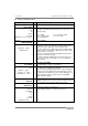
FCt. 1.6
PULSE OUTPUT
→
Pulse output
Settings for the pulse output
Characteristic, see Fig. 3 in Section 2.3
Only possible when “Pulse output” is set under Fct. 3.5
Hardware.
When “Status output” selected, Fct. 1.6 has “no function".
inFo
Function
↵
Function
Edit
off
PoS.direction
neG.direction
↑
abSolute
Standard: absolute
↵
Setting of the characteristic of the pulse output
“off” = switch at output open
Other selection
inFo
PulSe width
↵
Pulse width
Minimum interpulse period = half pulse width
XXX0.
mS
Range 30 ... 1000 ms
Standard: 50 ms
↵
Pulse width defines the time during which the switch at the
output is closed and high current flows between terminals B1
or B2 and B
⊥
. The maximum pulse rate is selected at the
same time, as the interpulse period is at least equal to half
the pulse width:
widthpulse1.5
1
rate Pulse
max
×
=
inFo
Pulse/Volume
↵
Pulses / Volume
Number of pulses per unit volume
XXX.XXX
m3
l
Gal.
↑
“
user unit"
Range 0 ... 10 Hz
Standard:
1 pulse per m3
↵
Pulses/Volume is used to set the number of pulses that are
output for the given volume. If 10.0 is set at Unit m
3
, 10
pulses are output per cubic metre. If 0.01 is set at Unit l , one
pulse is output per 100 litres.
•
A large pulse width together with a high pulse rate will
cause overranging. Therefore, pulse rate is limited so
that the minimum interpulse period does not drop below
half the pulse width. In that case, error message due to
overranging of the pulse output, i.e. marker flashes and,
if activated in Fct. 1.4 “Display", is output in the form of
horizontal scrolling.
•
When the pulse output is overranged, the missing pulses
are output later, at times of lower flow.