© KROHNE 02/2002 Remote Operation Instructions HART Communicator 275 Asset Management Solutions (AMS) Process Device Manager (PDM) IFC040 KROHNE Messtechnik GmbH & Co. KG · Ludwig-Krohne-Str. 5 D-47058 Duisburg Tel.: 0203-301 0 Fax: 0203-301 389 · e-mail: krohne@krohne.
Remote Operation Instructions IFC040 HART 1 General Information 3 2 IDs and Revision numbers 3 3 Implementation Peculiarities 3 4 HART Communicator 275 (HC275) 3 5 6 4.1 Installation 3 4.2 Operating 3 Asset Management Solutions (AMS) 4 5.1 Installation 4 5.2 Operating 4 Process Device Management (PDM) 4 6.1 Installation 4 6.2 Operating 4 KROHNE Messtechnik GmbH & Co. KG · Ludwig-Krohne-Str. 5 D-47058 Duisburg Tel.: 0203-301 0 Fax: 0203-301 389 · e-mail: krohne@krohne.
Remote Operation Instructions IFC040 HART 1 General Information The IFC040 is a two-wire transmitter with 4...20mA current output and HART capability. General Characteristics of the IFC040 HART interface: • Multidrop Mode is supported • Burst Mode is not supported Electrical connection: Refer to sections 2.1, 2.2 of the “Installation and Operating Instructions. ALTOFLUX 2W IFM 4042 K. Electromagnetic flowmeters”, Feb. 2001.
Remote Operation Instructions IFC040 HART 5 Asset Management Solutions (AMS) 5.1 Installation If the IFC040 Device Description is not already installed on the AMS System a so called Installation Kit IFC040 HART AMS is needed (available on floppy disk from KROHNE or as download from KROHNE Internet page). For installing the DD with the Installation Kit refer to the “AMS User's Guide” section 3:”Managing HART Devices” / “Adding new Device Types to AMS” / “Install Device Types Manually”. 5.
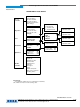
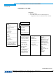
Remote Operation Instructions IFC040 HART Attachment A IFC040 Menu Tree HC275 1 Process Variables 2 Operation 1 Raw Flow 2 Smoothed Flow 3 Positive Totalizer 4 Negative Totalizer 5 Current Output Value 6 PV %Range 1 Full Scale 2 Time Constant 3 Cutoff ‘On’ value 4 Cutoff ‘Off’ value 5 Display 1 Loop Test 2 Hardware Info 3 Sensor Limits 3 Test (M) 1 Apply values 2 Zero trim 3 HART (M) (M) 5 Quit/Reset 1 Counter reset 2 Error reset 3 Master reset (M) (M) (M) 6 HART Variables 1 Tag 2 Device Id 3 F
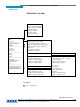
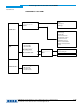
Remote Operation Instructions IFC040 HART Attachment B IFC040 Menu Tree AMS • Flow • Flow, scaled by URV/LRV • Flow, scaled by USL/LSL • Positive Totalizer • Negative Totalizer • Current Output • Flow, Percent Range Process Variables Status Scan Device ----------------------------------Diagnostics and Test Calibrate ----------------------------------Error reset Counter reset Master reset ----------------------------------Assign Unassign Rename ----------------------------------Audit Trail Record Manual E
Remote Operation Instructions IFC040 HART Attachment B IFC040 Menu Tree AMS Designations: Rd – Read-only variable; Loc – Local AMS variable, affects only AMS faceplates and configuration tabs and is not read/written from/to instrument.
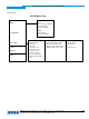
Remote Operation Instructions IFC040 HART Attachment C IFC040 Menu Tree PDM • Tag • Descriptor • Message Operation Unit ----------------------Device Identification Input • Time Constant • Cut On Value • Cut Off Value -----------------------Mesuring Limits ----------------------Process Value Scale • Manufacturer ID • Devicetype • Device ID • Universal revision • Transmitter revision • Software revision • Hardware revision • Sensor serial number • Final assembly number • Date Flow -------------------Fl
Remote Operation Instructions IFC040 HART Attachment D IFC040 Menu Device Communication Way Set Address Load to Device Load to PG/PC • Loop Test Test • Counter reset • Error reset • Configuration flag reset • Master reset Reset / Quit Sensor calibration Analog Output • Apply Values • Zero Trim Primary Value Hart Communication • I 4 mA Trim • I 20 mA Trim KROHNE Messtechnik GmbH & Co. KG · Ludwig-Krohne-Str. 5 D-47058 Duisburg Tel.: 0203-301 0 Fax: 0203-301 389 · e-mail: krohne@krohne.
Remote Operation Instructions IFC040 HART Attachment E IFC040 Menu View Display Yt – Diagramm Device Status Toolbar Statusbar Update Measured Value • Flow • Flow, scaled by URV/LRV • Positive Totalizer • Negative Totalizer Output • Current Output • Flow, Percent Range Device • Manufacturer ID • Devicetype • Device ID • Universal revision • Transmitter revision • Software revision • Hardware revision • Sensor serial number • Final assembly number • Date Hardware Info • ADC module dynamic status • I