© KROHNE 11/2003 7.30926.31.00 GR Ultrasonic Flowmeters ALTOSONIC V Addition to the installation and operating instructions EEx Operating Manual UFC/V...-EEx ultrasonic flow converter UFS 500 F/5STR/...
General advice on safety • • • • • • • • • • Do not install, operate or maintain this flowmeter without reading, understanding and following the factory-supplied instructions, otherwise injury or damage may result. Read these instructions carefully before starting installation and save them for future reference. Observe all warnings and instructions marked on the instrument. Use only mains supply with protective earthing connected. Do not use the instrument with removed covers under wet conditions.
Disclaimer • • • • • This document contains important information on the instrument. KROHNE attempts to be as accurate and up-to-date as possible but assumes no responsibility for errors or omissions. Nor does KROHNE make any commitment to update the information contained herein. This manual and all other documents are subject to change without prior notice.
This instrument is developed and manufactured by: KROHNE Altometer Kerkeplaat 12 3313 LC Dordrecht The Netherlands For information, maintenance or service please contact your nearest local KROHNE representative. WARNING ! No changes may be made to the devices. Unauthorized changes might affect the explosion safety of the devices.
Table of Contents 1. 1.1 1.2 1.3 1.3.1 1.3.2 1.3.3 1.3.4 2. 2.1 2.2 2.3 3. 3.1 3.2 3.3 3.3.1 3.3.2 3.4 System components..........................................................................2 General information .................................................................................... 2 Flow Sensor ................................................................................................ 2 Flow Converter................................................................................
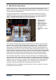
1. System components 1.1 General information The ALTOSONIC V ultrasonic flowmeter system, consisting of a combination of the UFS 500 F/5STR-EEx Ultrasonic Flow Sensor and the UFC-V/…-EEx Ultrasonic Flow Converter, in separate design, is in accordance with the European Directive 94/9 EG (i.e. ATEX 100a) and approved for hazardous classified locations of Zone 1 and 2 by the PTB conform to the European Standards of the EN 500xx series.
Both consist of an approved flameproof box, in which five UFC 500…-EEx electronics units and the connecting terminals are installed. The low-temperature version is additionally provided with a heating element of maximum 200 W power, which is controlled by a thermostat to keep the temperature inside the flameproof box above -20°C. The standard (20°C) version can optionally be provided with a heating element of maximum 30 W and thermostat, to prevent condensation inside the flameproof box.
The second thermostat T2 is a bi-metal controlled thermoswitch that is set to ca. -20°C switching temperature, meaning that when the air-temperature inside the flameproof box exceeds -20°C, the contact closes. Thermostat T2 is connected in series with the live of the five UFC 500…-EEx electronics units, so above an air-temperature of approx. -20°C, the five UFC 500…-EEx units are provided with the supply power and start operating.
2. Electrical connections The two types of UFC-V/…-EEx Ultrasonic Flow Converter have almost the same connection facilities, except that the standard (with optional heater) and the low-temperature version type UFC-V/LT-EEx are provided with three additional terminals (L, N and PE) for connection of thermostat(s) and heating element. The figure below shows the non-intrinsically safe connection terminals of the optional standard UFC-V/EEx version with 30 W heater and the UFC-V/LT-EEx low-temperature version.
2.1 Equipotential bonding system The UFC-V/…-EEx Ultrasonic Flow Converter with cable glands must always be incorporated into the equipotential bonding system with the UFS 500 F/5STR-EEx 5-beam Flow Sensor. If the UFC-V/…-EEx is provided with metal rigid conduits, equipotential bonding is not required but can optional be connected. The bonding conductor must have a minimum cross-sectional area of 2.
2.3 Connection diagram RS485 data communication 1 2 ⊥ Power supply heater Power supply UFC 500's 110-240Vac/dc; 50/60Hz 24-240Vac; 50/60Hz or @ max. 200W or 24Vdc 24Vdc @ max. 30 W.
3. Service and maintenance 3.1 Introduction Both UFC-V/…-EEx types are maintenance regarding flowmetering properties. Within the scope of the periodical inspections, required for electrical instruments that are installed and used in hazardous classified locations, it is recommended to check the flameproof enclosure. Contact KROHNE for the ordering information of spare parts or replacements of UFC 500/…EEx electronics units and/or power fuses.
• • Before the cover is bolted back onto the flameproof box, the flanged joint as well as the screw-thread of the bolts must be clean and well-greased with an acid and resin-free grease, e.g. silicone grease. Screw all bolts tightly into the box with the right size socket-head screw wrench. A 1 1. Coaxial cables (intrinsically safe) 2. SMB plugs (intrinsically safe) 3. Heater 4. Mounting bushing 5. Mounting plate B 2 C 3 4 5 Figure 3a: Side view of assembled mounting plate of UFC-V/LT-EEx 1.
1. Unscrew all bolts of the flameproof box and open the cover. 2. Disconnect the SMB connectors of the coaxial cables, the 3-pole power supply connector and 5-pole connector of the in-/output circuits at the electronics unit(s) involved. 3. Unscrew the two screws A of the display unit and turn display unit carefully aside or remove the unit completely by taking out the flat cable connector. 4.
3.3.2 24 V AC/DC version Before commencing work, note the "Before opening" instructions, then continue as follows: 1. Unscrew the bolts and open the cover of the flameproof box. 2. Unscrew screws A of the display unit and disconnect it via the flat cable connector. 3. Unscrew the copper earth strip (screw C) and the mounting screws B of the electronics unit. Disconnect the SMB connectors and the 3-pole and 5-pole connectors. Then take the complete electronics unit out of the box. 4.
Appendix 1 Type Examination Certificate PTB Certificate PTB 01 ATEX 2012 EEx UFS 500 F/…/…/…-EEx German original page 1-3 ALTOSONIC V 12
ALTOSONIC V 13
ALTOSONIC V 14
PTB Certificate PTB 01 ATEX 2012 EEx UFS 500 F/…/…/…-EEx English translation page 1-3 ALTOSONIC V 15
ALTOSONIC V 16
ALTOSONIC V 17
KEMA ATEX certificate 02ATEX2168 ALTOSONIC V UFC-V/EEx and UFC-V/LT-EEx ALTOSONIC V 18
ALTOSONIC V 19
ALTOSONIC V 20
ALTOSONIC V 21
Appendix 2 Declaration of Conformity ALTOSONIC V 22
Appendix 3 Data plates Standard UFC-V/EEx Ultrasonic Flow Converter Standard version UFC-V/EEx with optional 30 W heater Low-temperature version UFC-V/LT-EEx UFS 500 F/5STR-EEx Flow Sensor (cable gland design) NOTE: The heating element may have a maximum power dissipation of 200 W. The current heating element has a power dissipation of approx. 130 W.
Australia KROHNE Australia Pty Ltd. Unit 19 No. 9, Hudson Ave. Castle Hill 2154, NSW TEL.: +61(0)2-98948711 FAX: +61(0)2-98994855 e-mail: krohne@krohne.com.au Austria KROHNE Austria Ges.m.b.H. Modecenterstraße 14 A-1030 Wien TEL.: +43(0)1/203 45 32 FAX: +43(0)1/203 47 78 e-mail: info@krohne.at Belgium KROHNE Belgium N.V. Brusselstraat 320 B-1702 Groot Bijgaarden TEL.: +32(0)2-4 66 00 10 FAX: +32(0)2-4 66 08 00 e-mail: krohne@krohne.be Brazil KROHNE Conaut Controles Automaticos Ltda.