
User guide


ALTOSONIC V 5
2. Electrical connections
The two types of UFC-V/…-EEx Ultrasonic Flow Converter have almost the same connection
facilities, except that the standard (with optional heater) and the low-temperature version
type UFC-V/LT-EEx are provided with three additional terminals (L, N and PE) for connection
of thermostat(s) and heating element.
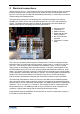
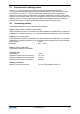
The figure below shows the non-intrinsically safe connection terminals of the optional
standard UFC-V/EEx version with 30 W heater and the UFC-V/LT-EEx low-temperature
version. The default standard version is identical, but without the two thermostats and
additional terminals for the heating element and thermostat T1.
1. Heating element
2. Thermostat T1
3. SMB connectors
4. Sticker with terminal
label information
5. Non-intrinsical safe
terminals
6. Thermostat T2 (under
plate)
Figure 1: Non-intrinsically safe terminals of UFC-V/LT-EEx
The connection facilities inside the approved flameproof box consist of a terminal rail with
terminals for the non-intrinsically safe connections: supply power (L, N and PE) for the five
UFC 500…-EEx electronics units, the RS485 communication units (1, 2 and ⊥) and the
supply power for the heating element and thermostat (L, N and PE), which applies for the
low-temperature version UFC-V/LT-EEx and the optional standard version with max. 30 W
heater. The ground connection consist of a cable lug that is screwed into the mounting plate
or the bulge that is casted within the bottom of the box. The mounting plate is screwed to the
bulges in the corners at the bottom of the flameproof box by four screws with spring or
toothed washers. Herewith all metal parts are electrically connected to ground potential.
The intrinsically safe ultrasonic sensor circuits are connected to the ten SMB receptacles
(two rows of five male-to-male connectors), which are screwed into the metal terminal plate
at the left side of the non-intrinsically safe terminals. The SMB receptacles are marked by the
numbers x.1 up to x.2, where x = 1 through 5. The marking consists of a white sticker with
black printed number. The SMB plugs that are to be connected to these receptacles are
marked by a yellow plastic tubing with the matching black printed number.
Equipotential bonding is established via the external bolt, which is screwed into a bulge on
the outside of the box at the base.
1
2
3
4
5
6