
Manual


ALTOSONIC V
ModBus Manual 0300 rev07 E 7.30855.35.00 Page 23 of 64
7.3 Software set-up
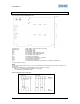
Now set-up the software, all the settings for the Modbus driver is done in the file [coms0300.dat].
See also chapter 9.4 Appendix D: Coms0300.dat file
7.3.1 First set the parameters for the communication line
• 3.1 MODBUS_UART_BASEADRESS for channel 1 is COM4 this is baseaddress 0x2E8
• 3.2 MODBUS_UART_INTERRUPT is for COM4 set to interrupt 3.
• Depends on your application : 3.3 MODBUS_UART_BAUDRATE 1200,2400,4800,9600,19200
• 3.4 MODBUS_UART_RTS_MODE to 0.
• Depends on your application : 3.5 MODBUS_UART_N_DATABITS to 7 or 8
• Depends on your application : 3.6 MODBUS_UART_N_STOPBITS to 1 or 2
• Depends on your application : 3.7 MODBUS_UART_PARITY to none, even or odd.
• Depends on your application : 3.3 MODBUS_UART_BAUDRATE 1200,2400,4800,9600,19200
• Depends on your application :
If you use RS485 set 3.8 MODBUS_UART_HALF_DUPLEX to HALF_DUPLEX(=1)
If you use RS422 set 3.8 MODBUS_UART_HALF_DUPLEX to FULL_DUPLEX(=0)
7.3.2 Now select the parameters for the used protocol
• Select the frame type RTU or ASCII with 3.9 MODBUS_TRANSFER_MODE.
• Set the UFP-V as MASTER or SLAVE device with 5.1 MODBUS_DEVICE_TYPE.
• Select if variables, which are larger than 16 bits are still counted as the number of 16 bit
• Set the data points requesting type by parameter 5.2 MODBUS_MODICON_COMPAT:
By type is not modicon compitable ( =0)
By 16 bit registers is modicon compitable ( =1)
•
7.3.3 The UFP-V as SLAVE device
The slave mode is activated when the parameter 5.1 MODBUS_DEVICE_TYPE=1.
• If the UFP-V acts like a Modbus Slave device, set the SlaveID with 5.3 MODBUS_SLAVE_ID.
• The 5.4 FLAG_HOLD_TIME is a hold time on the status flags (Booleans only).
The 5.4 FLAG_HOLD_TIME freezes the flags after the flag has changed from state.
Set this time a bit larger than the maximum communication-request interval.
• The next fields define to which Modbus addresses the data of the UFP-V is mapped to, these
settings are default settings and should not be changed, only if necessary.
The fields are 6 DATAFIELD 1 to N, for every DATAFIELD an access mode could be set.
The 6 ACCES MODE defines how the data is send and interpreted when the UFP-V is in slave-
mode.
• See the manual of the accompanying byte-order of transmission/reception with the 2 modes.
For Slave-use the driver should be working now.