
Manual


MODBUS PROTOCOL DESCRIPTION AND SET-UP 10
113
ALTOSONIC V12
www.krohne.com04/2013 - 4002643502 - MA ALTOSONIC V12 R02 en
10.3.2 RTU mode
Each byte of data is represented in the message by an equivalent number of bits (8).
The number of bits transmitted in the process of communicating one byte of information is
sometimes also referred to as a “character”.
Note that this is not the same as an ASCII character.
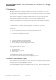
Standard serial communication parameters
10.4 Modbus message framing
ASCII mode
In ASCII mode a message starts with a colon character (:) and ends with a carriage return-
linefeed. Intervals up to one second can elapse between characters within the message. If the
interval is longer, a timeout error occurs and the message is rejected.
RTU mode
In RTU mode a message starts with a silent time interval equivalent to at least 3.5 characters.
The entire message frame must be transmitted as a continuous stream. If a silent interval of
more than 3.5 character times occurs before completion of the frame, the receiving device
flushes the incoming message and assumes that the next byte will be the address field for the
new message.
Start bits 1
Data bits 8
Parity even
Stop bits 1
Error check
field
Cyclic Redundancy Check (CRC)
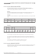
Mode Start Address Function Data Checksum End
ASCII-mode 2 characters 2 characters N*2
characters
LRC 2
characters
CR-LF
RTU-mode 3.5
characters
silent
interval
8 bits 8 bits N*8 bits CRC 16 bits 3.5
character
silent
interval
Table 10-1: Example of a typical message frame