© KROHNE 7.02568.21.00 18.10.2005 Installation and operating instructions BATCHCONTROL 5014 C Compact Electromagnetic Flowmeters with CANopen bus interface Please note! Do not open the housing of the BATCHCONTROL 5014C. Danger of contamination with substances likely to destroy the moisture barrier of the electronic equipment (e.g. if CIP or SIP cleaned from the outside). Therefore, please contact your KROHNE Service engineer before you open the housing.
Contents System description Standards and approvals Product liability and warranty Functional description BATCHCONTROL IFM 5014C Part A System installation and start-up 2 BATCHCONTROL 4 4 4 5 6 - 15 1 1.1 1.2 1.3 1.3.1 1.3.2 1.3.3 1.4 1.4.1 1.4.2 1.5 1.5.1 1.5.
8 Measuring principle 28 Part E Annex 29 - 47 E1 E2 E3 29 30 - 45 46 Index CAN parameter Form to accompany returned device Please note! Do not open the housing of the BATCHCONTROL IFM 5014C. Danger of contamination with substances likely to destroy the moisture barrier of the electronic equipment (e.g. if CIP or SIP cleaned from the outside). Therefore, please contact your KROHNE Service engineer before you open the housing.
System description The BATCHCONTROL IFM 5014C compact electromagnetic flowmeter is a precision instrument designed for the linear flow measurement of liquid products and controlling the filling process. The products need to be electrically conductive: > 5 µS/cm (except for water) > 20 µS/cm (for water) The full-scale range Q100% can be set as a function of the meter size: 1 1 Q100% = 0.0015 - 15 l/s DN 2.5 – 40 and /10” – 1 /2” This is equivalent to a flow velocity of 0.2 - 12 m/s.
Functional description BATCHCONTROL IFM 5014C The volume to be filled into the container is measured “in line“ by means of the electromagnetic flowmetering system. The BATCHCONTROL closes the filling valve once the preset filling volume has been reached. It is always the preset target volume that is filled into the container. The signal converter converts the measured flowrate signal into volume that are transfered to the integrated batch controller.
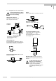
1 Part A System installation and start-up 1 Installation in the pipeline 1.1 Important information The following recommendations should be observed to ensure proper functioning of the flowmeter – PLEASE NOTE. • • • • • • • • • • 6 BATCHCONTROL Measuring tube must be filled completely at all times. Direction of flow: the blue arrow on the housing of the primary head must point in the direction of flow.
1 1.
1 1.3 Installation requirements Items supplied with flowmeter • • • Requirements BATCHCONTROL IFM 5014C compact flowmeter in the version as ordered Installation and operating instructions, as agreed Certificate of system calibration data (as agreed) Excluding fitting accessories. Stud bolts, gaskets, etc., to be provided by customer. All operating data and function values are factory set according to your order specifications.
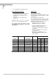
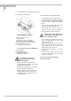
1 1.3.1 Position of flanges 1.3.3 Grounding Install flowmeter in line with the pipe axis. Pipe flange faces must be parallel to each other, max. allowable deviation: Lmax – Lmin ≤ 0.5 mm ≤ 0.02" V V R 1.3.2 Example: centering and sealing the primary head The primary head is centered between the pipe flanges with the aid of the precise geometric fitting (guide collar on primary head). Detail drawings see Sect. 1.5. RF FE FE R RF V R RF 2 Functional ground, wire > 4 mm Cu.
1 1.4 Installation of the primary head 1.4.1 Device description 1.4.
1 1.5 Size of connections 1.5.1 Fastening with tie bolts All dimensions in mm (inches) Flange-material: AISI 300 series O-ring material: 3A standard 18-03 Meter size DN inches 1 2.5 /10 4 1 6 1 10 3 15 1 25 1 32 1 /4 40 1 /2 /8 /4 /8 /2 1 1 Centering device, pipe connection di D1 D2 h 6 25.5 30 -0.05/-0.15 1.5 -0.05/-0.15 (0.24) (1.00) (1.18 -0.002/-0.006) (0.06 -0.002/-0.006) 7 25.5 30 -0.05/-0.15 1.5 -0.05/-0.15 (0.28) (1.00) (1.18 -0.002/-0.006) (0.06 -0.002/-0.006) 9 25.5 30 -0.
1 1.5.2 Fastening with bolts (option) All dimensions in mm (inches) * Flange-material : AISI 300 series O-ring material : 3A standard 18-03 Meter size DN 2.5 12 BATCHCONTROL inches 1 /10 4 1 6 1 10 3 15 1 /8 /4 /8 /2 Centering device, pipe connection di 6 (0.24) 7 (0.28) 9 (0.35) 12 (0.47) 14 (0.55) D1 25.5 (1.00) 25.5 (1.00) 25.5 (1.00) 25.5 (1.00) 25.5 (1.00) D2 30 -0.05/-0.15 (1.18 -0.002/-0.006) 30 -0.05/-0.15 (1.18 -0.002/-0.006) 30 -0.05/-0.15 (1.18 -0.002/-0.006) 30 -0.05/-0.15 (1.
2 Electrical connection 2.1 Important information Be sure to take note of the following information in order to ensure proper functioning of the signal converter. Please note: 1) Overvoltage class: In conformity with VDE 0120, equivalent to IEC 664, the compact flowmeters are designed for overvoltage category III in the supply circuits and overvoltage category II in the output circuits. 2) Safety isolation: The compact flowmeters must be provided with an isolating facility.
2 2.3 Power supply and CAN bus 5-pin connector M12x1 for 24V DC power supply and CAN bus Pin assignment Pin Description 1 ground CAN bus 2 +24 V power 3 ground 4 CAN high level 5 CAN low level 2.4 Input and output 8-pin connector M12x1 for 24V DC power supply and input / output signals Pin assignment Pin Description 1 input / output 1 2 input / output 2 3 input / output 3 4 input / output 4 5 input / output 5 6 input / output 6 7 +24 V power 8 ground 2.
3 3 Start-up Before powering the system, check that it has been installed correctly according to Sections 1 and 2. The compact flowmeter is delivered ready for operational use. All operating data have been factory set in accordance with your specifications. Power the unit, and the flowmeter will start process flow measurement immediately. 3.1 Check for availability Please note! Do not open the housing of the BATCHCONTROL IFM 5014C.
4 Part B IFC 014 batch controller 4 Description of functions Six contacts are available for the different functions. Every contact can be switched over as a switching output, switching input or analogous by software. In addition, the device has one CAN bus interface for communication, two internal temperature sensors and one flow sensor . 4.
4 The object dictionary for the parameters is subdivided into the following groups: Object number range 10xxH 300xH 301xH 302xH 303xH 304xH 305xH 306xH 307xH 308xH 309xH 30AxH 32xxH 33xxH 34xxH 35xxH Description CAN open parameter Flow sensor parameter Electronic temperature sensor Liquid temperature sensor Function block 1 Function block 2 Function block 3 Function block 4 Function block 5 Function block 6 Batching CAN parameter Customer specific 1 bit memory Customer specific 8 bit memory Customer speci
4 volume. Output ‘3’ is used for the carbonizing of the bottle. This valve ist used at the beginning of the filling process. It opens for 0,6 second. Output ‘4’ is used for unpreasurizing the bottle at the end of the filling process. It opens for 1 second. Output ‘5’ an ‘6’ are not used. CAN PARAMETER Letter output 1 output 2 output 3 output 4 output 5 output 6 Object No. 3031.01 3034.01 3041.01 3044.01 3051.01 3054.01 3061.01 3064.01 3071.01 3081.
H 3064.02 3064.03 3064.05 3064.06 3091.03 I G–J 4 Output 4 on function definition On value (output 4) Output 4 off function definition Off value (output 4) Time out There are parameters similar as in the case of the time representation, for the supervision of the volume flow. volume flow parameter flow 0,16 max. limit flow max.
4 filling is completed to 'D'. The parameter ‘I’ is the switch point for lower speed and ‘H’ is the target volume. ‘E’, ‘F’ and ‘G’ are alarm and emergency shutoff values. CAN PARAMETER Letter B E F G H I Object No. 3091.02 3093.04 3003.05 3093.01 3091.01 3044.06 Description Forward run time Maximum batching time Maximum volume Maximum tail volume Target volume Off value As a rule, valves don't close directly and completely. It comes to vibrations if the liquid is suddenly stopped.
5 Part C Service 5 5 Illustration of printed circuit board Please note! Do not open the housing of the BATCHCONTROL IFM 5014C. Danger of contamination with substances likely to destroy the moisture barrier of the electronic equipment (e.g. if CIP or SIP cleaned from the outside). Therefore, please contact your KROHNE Service engineer before you open the housing.
6 Part D Technical Data, block diagram and measuring principle 6 Technical data 6.1 Flow during filling, and fill volume Meter size DN mm 6.2 22 BATCHCONTROL inches 1 2.5 4 6 10 15 25 32 40 /10 /8 1 /4 3 /8 1 /2 1 11/4 11/2 1 Filling times > 1.5 s, filling volume ..... ml US Gal Optimum flowrate for filling ml/s 3 10 20 60 150 400 650 1000 - US Gal/min 10 30 60 200 500 1200 2250 3000 0.048 0.159 0.317 0.951 2.378 6.340 10.300 15.850 - ≥ ≥ ≥ ≥ ≥ ≥ ≥ ≥ 0.159 0.476 0.951 3.170 7.925 19.020 35.
6 6.3 Signal converter Power supply Voltage 24 V DC, ± 20% Power consumption ≤ 5 W excl. external loads Electrical connection two M12 plug-in connector Operator control All operating data factory-set to your specifications. Available as option for change of operating data: - KROHNE software for operator control via PC.
6 6.4 Error limits at reference conditions F MV = Error in % of MV = measured value Pulse output at flow velocity of ... v ≥ 1 m/s ≥ 3.3 ft/s v < 1 m/s < 3.3 ft/s Repeatability DN 2.5 – 6 / 1/10“ – 1/4“ DN 10 – 40 / 3/8“ – 11/2“ F < ± 0.5 % of MV F < ± 0.4 % of MV + 1 mm/s < ± 0.4 % of MV + 0.04 inch/s F < ± 0.3 % of MV F < ± 0.2 % of MV + 1 mm/s < ± 0.2 % of MV + 0.04 inch/s Filling time TF 1.5 s < TF ≤ 3 s 3.0 s < TF ≤ 5 s 5.0 s < TF Standard deviation σ ≤ 0.4 % ≤ 0.2 % ≤ 0.
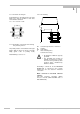
6 6.5 Dimensions and weights in mm (inches) 1 DN 2.5 –15 / /10“ – ½“ M12 connector series 713, 5 and 8-pin flow direction M6 X2 option: 4 x M6 bolt hole on both sides (section M-M) Meter size DN 2.5 4 6 10 15 inches 1 /10 1 /6 1 /4 3 /8 1 /2 Diameter d1 mm 6 7 9 12 14.3 (inches) (0.24) (0.28) (0.35) (0.47) (0.56) Weight kg 1.6 1.6 1.6 1.6 1.6 lb (3.6) (3.6) (3.6) (3.6) (3.
6 DN 25 – 40 / 1“ – 1½“ M12 connector series 713, 5 and 8-pin Meter size Dimensions in mm (inches) DN inches a 25 1 58 (2.28) 200 (7.87) 66 (2.68) 34 (1.34) 1.6 (3.6) 1 b Weight f g kg (lb) 32 1 /4 83 (3.27) 215 (8.46) 81 (3.19) 42 (1.65) 2.3 (5.1) 40 1 /2 1 83 (3.27) 215 (8.46) 81 (3.19) 42 (1.65) 2.3 (5.1) 6.6 Instrument nameplates Type designation Serial No.
7 7 Block diagram The IFC 014 signal converter consists of 2 functional groups. Functional group 1 contains an input amplifier, and a high-resolution analog/digital converter that is controlled and monitored by microprocessor CPU 1. It controlled also the direct current for the field coils of the primary head. Functional group 2 is the batch controller board. It is supdevided in the six IO-function blocks, the CAN bus interface and the temperature sensors. All functions are controlled by the CPU 2.
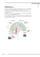
8 8 Measuring principle Flowmeter for electrically conductive liquids. Measurement is based on Faraday’s law of induction, according to which a voltage is induced in an electrically conductive body passing through a magnetic field.
E E1 E Index Part E Annex Keyword A Ambient temperature B Block diagram IFC 014 C Section-No. Fct-No. inches 6.2, 6.5 1.5, 6.1, 6.5 1.1, 6.2 6, 7 C Keyword Cleaning Connection diagrams – outputs – power supply Connection points – grounding D Data, Technical Device description DN = meter size in mm O Operating pressure Option 2.4 2.
r - - Description 0 transfer long Descriptor min without access Format Device type max Dimension Description Value (default) CAN parameter Index E2 Object No E 10xxH CANopen parameter 1000H 00H 0x00000014 (const.
03H 0,0 3002H 04H 4 Volume flow with time constant Sending function for Index 03H Description transfer Descriptor access max min Format Dimension Description Value (default) Index Object No 3002H l/s float -15,1 15,1 r 02H - without byte 0 4 r/w - d 1 = no message output 0 = activation of message output actual measurement flow value with time constant Sending function Measurement value with time constant Bit 1-0: Priority 00 = PDO 0 01 = PDO 1 10 = PDO 2 11 = PDO 3 3002H 05
3003H 07H 08H Description transfer Descriptor access max min Format Dimension Description Value (default) Index Object No 3003H - Actual status without byte 0 1 r 05H - 4 Sending function for Index 07H without byte 0 4 r/w - d volume is to high, 0 = no influencing of the output Bit 1: 1 = output 2 switch off if volume is to high, 0 = no influencing of the output Bit 2: 1 = output 3 switch off if volume is to high, 0 = no influencing of the output Bit 3: 1 = output 4 switch of
Description transfer Descriptor access max min Format Dimension Description Value (default) Index Object No Bit 1-0: Priority 00 = PDO 0 01 = PDO 1 10 = PDO 2 11 = PDO 3 Bit 2: activation of function 0 = activation of message output 1 = no message output 302xH Liquid temperature sensor 3021H Sensor parameter 3021H 00H 2 Number of entries without byte - - r - - 3021H 01H 1.0 Factor for scaling without float 0,001 1000 r/w - d 3021H 02H 0.
Description transfer Descriptor access max min Format Dimension Description Value (default) Index Object No 0000 = off 0001 = binary input 0010 = analogue input 0011 = binary output 0100 = pulse width modulated output 0101 = customer program 30y2H Binary input parameter and PDO definition (only valid if 30y1.
02H 1,0 Scaling factor for analogue input without float 0,0001 1000 r/w - as 30y3H 03H 0,0 Scaling offset for analogue input V float -1000 1000 r/w - as 30y3H 04H 0,0 V float 0,0 1000 r y2H - 30y3H 05H 4 Measured voltage (with scaling) Sending function for Index 04H without byte 0 4 r/w - Description transfer Descriptor access max min Format Dimension Description Value (default) Index Object No 30y3H d 0010 = start of batching 0011 = stop of batching (em
Description transfer Descriptor access max min Format Dimension Description Value (default) Index Object No ground 1 = output switching to +24V Bit1: output polarity 0 = high active 30y4H 02H 30y4H 03H 30y4H 04H 0 Output on function definition 0,001 On value s 0 Input channel for on signal without byte 0 11 r/w - d l or s or V or °C float 0s 0l 0l/s 0V -20°C 100s 100l 15l/s 11V 120°C r/w - d without byte 0 31 r/w - d 1 = low active Bit 0-3: definition for switchi
Description transfer Descriptor access max min Format Dimension Description Value (default) Index Object No 1000 = switch off by analogue voltage 1001 = switch off by batch program 1010 = switch off by error detected 1011 = switch off by customer program 30y4H 06H 30y4H 07H 0,001 Off value s 0 Input channel for off signal l or s or l/s or V or °C without float 0s 0l 0l/s 0V -20°C 100s 100l 15l/s 11V 120°C r/w - d byte 0 21 r/w - d According to selected function: off time or
Description transfer Descriptor access max min Format Dimension Description Value (default) Index Object No 1 = counter operates Bit 1: Counter reset 0 = no function 1 = reset the counter 3091H 3091H 05H 06H 0 0 Controlling batching process Learning function without - byte byte 0 0 3 3 w r/w - - d d Bit 0: 1 = Start filling through bus, only at batching process = CAN Bus (0 = without function) Bit 1: 1 = Stop filling through bus, independent from other inputs (0 = without f
Description transfer Descriptor access max min Format Dimension Description Value (default) Index Object No 1 = wait 2 = fill 3 = tail 4 = pause 5 = break 3092H 02H 4 Sending function for Index 01H without byte 0 4 r/w - D Bit 4 - 7: not used Sending function at change of status Bit 1-0: Priority 00 = PDO 0 01 = PDO 1 10 = PDO 2 11 = PDO 3 Bit 2: Activation of function 1 = no message output 0 = activation of message output 3093H Alarm values and PDO definition 3093H 00H 3093H 01H
Description transfer Descriptor access max min Format Dimension Description Value (default) Index Object No output 3093H 08H 0,3 3093H 09H 0 4 3093H 0AH Maximum tail time s float 0,005 10 r/w - d Actual status without byte 0 1 r 94H - Sending function for Index 09H without byte 0 4 r/w - d 0 = activation of message output Limit value for the tail time, status info only Bit 0: 1 = Limit value overstepped, 0 = okay Sending function at change of status Bit 1-0: Prio
Description transfer Descriptor access max min Format Dimension Description Value (default) Index Object No 1 = all emergency flags will be reset 3094H Result of last batching and PDO definition 3094H 00H 15 Number of entries without byte - - r - - 3094H 01H 4 Sending function without byte 0 4 r/w - d Sending function batching results Bit 1-0: Priority 00 = PDO 0 01 = PDO 1 10 = PDO 2 11 = PDO 3 Bit 2: activation of function 1 = no message output 0 = activation of message o
Description transfer Descriptor access max min Format Dimension Description Value (default) Index Object No 0 = activation of message output 3095H Statistic 3095H 00H without byte r - - 3095H 01H -3000 Range 1 15 Number of entries µl Word -32700 32700 - - r/w - d 3095H 02H -1500 Range 2 µl Word -32700 32700 r/w - d Second limit 3095H 03H -500 Range 3 µl Word -32700 32700 r/w - d Third limit First limit 3095H 04H +500 Range 4 µl Word -32700 32700 r/w
Value (default) Dimension Format min max access Descriptor transfer 0 Bit no 6 without byte 0 1 r/w - d 32y1H 07H 0 Bit no 7 without byte 0 1 r/w - d 32y1H 08H 0 Bit no 8 without byte 0 1 r/w - d 32y2H 00H 8 Number of entries without byte - - r - - 32y2H 01H 0 Bit no 9 without byte 0 1 r/w - d 32y2H 02H 0 Bit no 10 without byte 0 1 r/w - d 32y2H 03H 0 Bit no 11 without byte 0 1 r/w - d 32y2H 04H 0 Bit no 12 without byte
03H 0 Byte no 10 without byte +127 255 33y2H 04H 0 Byte no 11 without byte -128 0 +127 255 r/w - - 33y2H 05H 0 Byte no 12 without byte -128 0 +127 255 r/w - - 33y2H 06H 0 Byte no 13 without byte -128 0 +127 255 r/w - - 33y2H 07H 0 Byte no 14 without byte -128 0 +127 255 r/w - - 33y2H 08H 0 Byte no 15 without byte -128 0 +127 255 r/w - - 33y2H 09H 0 Byte no 16 without byte -127 0 +127 255 r/w - - r/w - - Description transfer Descrip
Format min max access Descriptor transfer Number of entries without byte - - r - - 35y1H 01H 0 Data format without byte 0 255 r - - 35y1H 02H 0 Long no 1 without long 2.1e9 -2.1e9 3.4e3 -3.4e38 8 r/w - - 35y1H 03H 0 Long no 2 without long 2.1e9 -2.1e9 3.4e3 -3.
E3 Form to accompany returned device If you need to return flowmeters for testing or repair to KROHNE Your electromagnetic flowmeter • has been carefully manufactured and tested • and volumetrically calibrated in one of the world’s most accurate test rigs. This means that KROHNE can only service your flowmeter if it is accompanied by a certificate in line with the following model confirming that the flowmeter is safe to handle.