
Manual


Installation and operating instructions 10 BATCHCONTROL
1.4 Installation of the primary head
1.4.1 Device description
•
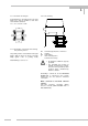
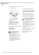
BATCHCONTROL IFM 5014C
4 Cover, signal converter
5 Primary head
7 Connector for the six in-/outputs
8 Connector for power and CAN Bus
9 U-clamp terminal for functional ground
10 Fastening screws for cover
11 Locating collar, primary head
•
Accessories from system manufacturer
12 O-ring gasket
13 Special pipe flange
14 Stud bolt with lock washer,
plain washer and nut
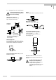
To facilitate servicing of the
primary head, please note the
following points:
•
It must be possible to shut off the flow
through the pipeline upsteam of the primary
head (provide shutoff valve),
•
Drain the pipe system before removing the
primary head (provide drain valve),
•
Support the pipeline on both sides of the
flowmeter when located in a long, freely
suspended section to facilitate removal of
the primary head.
1.4.2 Installation of the IFM 5014C
•
Position gaskets (12) in the pipe flanges.
•
Type and location of gaskets as specified
by the manufacturer of the filling machine
(see Sect. 1.3.2 “Centering of the primary
head”).
•
Insert primary head (5) between the pipe
flanges (13) in line with the pipe axis.
•
For spacing and location of the pipe
flanges, see Sect. 1.3 “Position of flanges”.
•
Press pipe flanges against flowmeter.
Centering ring of pipe flanges must
snap into place in the guide collar
(11) of the primary head.
•
Insert stud bolts (14) with washers into the
holes in the pipe flanges. Fit nuts to stud
bolts with lock washer.
•
Tighten stud bolts and nuts down to the
metal stop symmetrically. Check all bolts
after starting up the pipe system, and
retighten when any leaks show.
•
Connect ground conductor to U-clamp
terminal (9).
•
Connect power supply, CAN bus and
outputs to connector plugs (7, 8) on signal
converter housing (4).
See Section 2.2 and 2.3 for details of
electrical connection.
1