
Manual


Installation and operating instructions 14 BATCHCONTROL
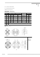
2.3 Power supply and CAN bus
5-pin connector M12x1 for 24V DC power supply and CAN bus
Pin assignment
2.4 Input and output
8-pin connector M12x1 for 24V DC power supply and input / output signals
Pin assignment
2.5 Block circuit diagram
The following picture shows the block circuit diagram of the BATCHCONTROL 5014C:
The individual functions of inputs and outputs are described in detail in the following chapter.
Pin Description
1 ground CAN bus
2 +24 V power
3 ground
4 CAN high level
5 CAN low level
Pin Description
1 input / output 1
2 input / output 2
3 input / output 3
4 input / output 4
5 input / output 5
6 input / output 6
7 +24 V power
8 ground
2