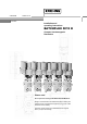
© KROHNE 7.30925.31.00 07.03.2003 Installation and operating instructions BATCHFLUX 5015 K Compact electromagnetic flowmeters Please note! Do not open the housing of the BATCHFLUX IFM 5015 K. Danger of contamination with substances likely to destroy the moisture barrier of the electronic equipment (e.g. if CIP or SIP cleaned from the outside). Therefore, please contact your KROHNE Service engineer before you open the housing.
Contents System description Standards and approvals Product liability and warranty Functional description BATCHFLUX IFM 5015 K 2 BATCHFLUX 4 4 4 5 Part A System installation and start-up 6 - 16 1 1.1 1.2 1.3 1.3.1 1.3.2 1.3.3 1.4 1.4.1 1.4.2 1.5 1.5.1 1.5.
Part C Special applications, functional checks, and service 36 - 42 6 6.1 6.2 Special applications RS 232 adapter and KROHNE software (option) Operation via HHT 010 hand-held terminal (option) 36 36 36 7 7.1 7.2 7.3 Functional checks Zero check with signal converter IFC 015 Test of measuring range Q, Fct. 2.1 Hardware information and error status, Fct. 2.2 37 - 39 37 38 39 8 8.1 8.2 8.3 8.
System description The BATCHFLUX IFM 5015 K compact electromagnetic flowmeter is a precision instrument designed for the linear flow measurement of liquid products. The products need to be electrically conductive: > 5 µS/cm (except for water) > 20 µS/cm (for water) The full-scale range Q100% can be set as a function of the meter size: DN 2.5 – 40 and 1/10” – 11/2” Q100% = 0.0015 - 15 l/s This is equivalent to a flow velocity of 0.3 - 12 m/s.
Functional description BATCHFLUX IFM 5015 K The volume to be filled into the container is measured “in line“ by means of the electromagnetic flowmetering system. The batch controller closes the filling valve once the preset filling volume has been reached. It is always the preset target volume that is filled into the container. The signal converter converts the measured flowrate signal into volume pulses that are intelligible to the batch controller.
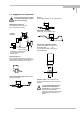
1 Part A System installation and start-up 1 Installation in the pipeline 1.1 Important information The following recommendations should be observed to ensure proper functioning of the flowmeter – PLEASE NOTE. • • • • • • • • • • 6 BATCHFLUX Measuring tube must be completed filled at all times. Direction of flow: the red arrow on the housing of the primary head must point in the direction of flow.
1 1.2 Suggestions for installation To avoid measuring errors due to air inclusion and vacuum, please observe the following: Pumps Do not install flowmeter on pump suction side Highest point of pipe run (Air bubbles collect in measuring tube - faulty measurements!) Open feed or discharge Install meter in low section of pipe Preferred locations open discharge downpipe (open discharge) Avoid draining or partial filling of the measuring tube. Faulty measurements.
1 1.3 Installation requirements Items supplied with flowmeter • • • Requirements BATCHFLUX IFM 5015 K compact flowmeter in the version as ordered Installation and operating instructions, as agreed Certificate of system calibration data (as agreed) Excluding fitting accessories. Stud bolts, gaskets, etc., to be provided by customer. All operating data and function values are factory set according to your order specifications.
1 1.3.1 Position of flanges 1.3.3 Grounding Install flowmeter in line with the pipe axis. Pipe flange faces must be parallel to each other, max. allowable deviation: Lmax – Lmin ≤ 0.5 mm ≤ 0.02" V V R 1.3.2 Example: centering and sealing the primary head The primary head is centered between the pipe flanges with the aid of the precise geometric fitting (guide collar on primary head). Detail drawings see Sect. 1.5. RF FE FE R RF V R RF 2 Functional ground, wire > 4 mm Cu.
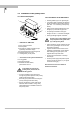
1 1.4 Installation of the primary head 1.4.1 Device description 1.4.
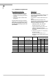
1 1.5 Size of connections 1.5.1 Fastening with tie bolts All dimensions in mm (inches) Flange-material: AISI 300 series O-ring material: 3A standard 18-03 Meter size DN inches 1 2.5 /10 4 1 6 1 10 3 15 1 25 1 32 1 /4 40 1 /2 /8 /4 /8 /2 1 1 Centering device, pipe connection di D1 D2 h 6 25.5 30 -0.05/-0.15 1.5 -0.05/-0.15 (0.24) (1.00) (1.18 -0.002/-0.006) (0.06 -0.002/-0.006) 7 25.5 30 -0.05/-0.15 1.5 -0.05/-0.15 (0.28) (1.00) (1.18 -0.002/-0.006) (0.06 -0.002/-0.006) 9 25.5 30 -0.
1 1.5.2 Fastening with bolts (option) All dimensions in mm (inches) * Flange-material : AISI 300 series O-ring material : 3A standard 18-03 Meter size DN 2.5 12 BATCHFLUX inches 1 /10 4 1 6 1 10 3 15 1 /8 /4 /8 /2 Centering device, pipe connection di 6 (0.24) 7 (0.28) 9 (0.35) 12 (0.47) 14 (0.55) D1 25.5 (1.00) 25.5 (1.00) 25.5 (1.00) 25.5 (1.00) 25.5 (1.00) D2 30 -0.05/-0.15 (1.18 -0.002/-0.006) 30 -0.05/-0.15 (1.18 -0.002/-0.006) 30 -0.05/-0.15 (1.18 -0.002/-0.006) 30 -0.05/-0.15 (1.18 -0.
2 2 Electrical connection 2.1 Important information • Be sure to take note of the following information in order to ensure proper functioning of the signal converter. • Please note: 1) Overvoltage class: In conformity with VDE 0120, equivalent to IEC 664, the compact flowmeters are designed for overvoltage category III in the supply circuits and overvoltage category II in the output circuits. 2) Safety isolation: The compact flowmeters must be provided with an isolating facility.
2 2.3 Power supply and outputs Standard 4-pin connector M12x1 for 24 V DC power supply and passive pulse output Pin Standard 1 + 24 V 2 pulse output 3 pulse output ⊥ 4 ground Pin assignment Pulse output passiv o ground p pulse output power 24 Volt DC Uext. ≤ Imax ≤ q n 30 V DC / ≤ 24V AC 20 mA The pulse output is galvanically isolated from the 24 V power supply. Pulse output • • • • • • All operating data and functions are settable (see Sect. 6).
3 3 Start-up Before powering the system, check that it has been correctly installed according to Sections 1 and 2. The compact flowmeter is delivered ready for operational use. All operating data have been factory set in accordance with your specifications. Power the unit, and the flowmeter will immediately start process flow measurement. 3.1 Check for availability Please note! Do not open the housing of the BATCHFLUX IFM 5015 K.
3 3.2 Factory settings All operating data are factory-set according to your order specifications. To facilitate easy and rapid initial start-up, pulse output is - unless specified otherwise set to process flow measurement in “2 flow directions“ so that the current flowrate is displayed and the volumetric flow counted independent of the direction of flow. The factory setting for the current and pulse outputs may occasionally cause measuring errors, particularly in the case of volume flow counting.
4 Part B IFC 015 signal converter 4 Operator control of signal converter with HHT 010 (option) 4.1 Operator control concept Please note! Do not open the housing of the BATCHFLUX IFM 5015 K. Danger of contamination with substances likely to destroy the moisture barrier of the electronic equipment (e.g. if CIP or SIP cleaned from the outside). Therefore, please contact your KROHNE Service engineer before you open the housing. 136.
4 4.2 Operating and check elements The following operating elements are featured on the hand-held communicator HHT 010: 4.3 Function of the keys The cursor, flashing part of display, has a grey background in the following descriptions. To start operator control Measuring mode HHT 010 1 3 . 5 7 1 190.47 m3/hr 3 m / h r → M Flowrate ← M + M M – Totalizer → ↵ M Operator control mode M → I P Overrange ↑ F c t . 1.
4 To change numbers Increase number 3 9 7. 3 5 ↑ 3 m / h r 3 9 7. 4 5 ↓ m3 / h r Decrease number To shift cursor (flashing position) Shift to right 3 9 7. 3 5 → 3 m / h r 3 9 7. 3 5 ← m3 / h r Shift to left To alter texts (units) For units, the numerical value is converted automatically Select next text 3. 7 6 9 9 ↑ L i t e r / S e c 9 3. 3 6 5 ↓ U S. G a l / m i n Select previous text To transfer from text (unit) to number setting Change to number setting 1 3.
4 4.4 Table of settable functions Abbreviatioins used DN Nominal size, meter size Fmax Highest frequency of the pulse output Fmin Lowest frequency of the pulse output FM Conversion factor volume for any unit, see Fct. 3.5 “FACT.VOL.“ FT Conversion factor time for any unit, see Fct. 3.5 “FACT.TIME“ GKL Primary constant I Current output (no HARDWARE) P Pulse output Pmax = Fmax / Q100% Pmin = Fmin / Q100% Q actual flow rate Fct. Text Description and settings 1.
4 Fct. Text 1.3 L.F. CUTOFF 1.4 DISPLAY → DISP. FLOW. → DISP. TOTAL. → DISP. MSG. Description and settings Fct. Text Description and settings 1.5 CURRENT I Current output I Low-flow cutoff (SMU) • OFF (fixed values: ON = 0.1% / OFF = 0.2%, at 100 Hz - 1000 Hz, see Fct.1.6, 1% and 2%) • PERCENT (variable values) ON 1 – 19% OFF 2 – 20% Press key → to transfer to number setting! Note: cutoff “off“ value must be greater than cutoff “on“ value! Press key ↵ to return to Fct. 1.3 L.F.
4 Fct. Text 1.6 Description and settings Fct. Text Description and settings → VALUE P Set pulse value per unit volume (appears only when “PULSE/VOL.“ set under “SELECT.P“ above) • xxxx PulS/m3 • xxxx PulS/Liter • xxxx PulS/US.Gal • xxxx PulS/ user unit, factory set is “Liter“ (see Fct. 3.5) Setting range “xxxx“ depends on the pulse width and the fullscale range: Pmin = Fmin / Q100% Pmax = Fmax / Q100% Press key ↵ to return to Fct.1.6 “PULS.OUTP.P“. 2.0 TEST Test menu 2.
4 Fct. Text Description and settings 3.0 INSTALL. Installation menu 3.1 3.2 LANGUAGE Select language for display texts • GB / USA (English) • F (French) • D (German) • others on request Press key ↵ to return to Fct. 3.1 “LANGUAGE“. FLOWMETER Set data for primary head Select size from table of → DIAMETER meter sizes • BATCHFLUX IFM 5015 K DN 2.5 - 40 mm equivalent to 1 1 /10 - 1 /2 inches Select with key ↑ or ↓. Fct. Text Description and settings → FIELD FREQ.
4 24 BATCHFLUX Fct. Text Description and settings 3.3 ZERO SET Zero calibration Note: Carry out only when flow is “0“ and measuring tube is completely filled! Precautionary query • CALIB. NO Press key ↵, return to Fct. 3.3 “ZERO“. • CALIB. YES Press key ↵ to start calibration. Duration approx. 10 seconds. Current flowrate displayed in the selected unit (see Fct. 1.4 “DISP.FLOW“) A “WARNING“ sign appears when flowrate “> 0“. Confirm with key ↵.
4 4.5 Error messages in measuring mode The following list gives all errors that are likely to occur during process flow measurement. Errors are shown in the display when “YES“ is set in Fct. 1.4 DISPLAY, subfunction “DISP.MSG.“. Error message Discription of error Error clearance LINE INT. Power failure Note: no counting during power failure Delete error message in RESET/QUIT menu. If necessary, reset totalizer. PULS.OUTP. P Pulse output overranged. Note: totalizer deviation possible.
4 4.6 Resetting totalizer and deleting error messages, RESET / QUIT menu Cancel error messages in RESET / QUIT menu Key Display Description ------- -----/--- Measuring mode CodE 2 -- Key in Entry Code 2 for RESET/QUIT menu: → ↑ ↑→ ERROR QUIT. Menu for error acknowledgement → QUIT. NO Do not delete error messages. Press ↵ twice = return to measuring mode. ↵ ↑ QUIT. YES Delete error messages ↵ ERROR QUIT.
Notes Installation and operating instructions BATCHFLUX 27
5 5 Description of functions Please note! 5.2 Do not open the housing of the BATCHFLUX IFM 5015 K. Danger of contamination with substances likely to destroy the moisture barrier of the electronic equipment (e.g. if CIP or SIP cleaned from the outside). Therefore, please contact your KROHNE Service engineer before you open the housing. 5.1 Full-scale range Q100% Fct. 1.1 FULL SCALE Press key → .
5 5.4 Display with HHT 010 Fct. 1.4 DISPLAY Press key ↵ . → DISP.FLOW = Select unit for display of flowrate, press key → • NO DISP. (not displayed) • m3/hr (cubic metres per hour) • Liter/Sec (litres per second) • US.Gal/min (US gallons per minute) • User-defined unit; factory-set is „Liter/hr“ (litres per hour), see Sect. 5.12 • PERCENT (percentage display) • BARGRAPH (numerical value and bar graph display in %) Select with keys ↑ and ↓. Press key ↵ to transfer to subfunction “DISP.COUNT“ → DISP.
5 5.6 Current output I Pulse output P No HARDWARE! Function must be set to “OFF”. Fct. 1.6 PULS.OUTP. P Press key → . Fct. 1.5 CUR.OUTP. I HARDWARE !) Press key → . → FUNCTION P = Select function for the pulse output, press key → • OFF (switched off, no function) • 1 DIR. (1 flow direction) • 2 DIR.
5 → VALUE P = Set pulse value per unit volume, (appears only when “PULSE/VOL.“ has been set under “SELECT P“) press key → 3 • XXXX PulS/m • XXXX PulS/Liter • XXXX PulS/US.Gal • XXXX PulS/ user-defined unit, factory-set is “Liter“, see Sect. 5.12. Select with keys ↑ and ↓. Transfer to number setting with key →, 1st digit (cursor) flashes.
5 5.8 Status output S (option) No HARDWARE! Function must be set to “OFF”. Transfer to number setting with key ↵, 1st digit (cursor) flashes. Change flashing digit (cursor) with keys ↑ and ↓, shift cursor 1 place to right or left with keys → and ←. Press key ↵ to return to Fct. 1.7 IND. OUTP. S. Fct. 1.7 IND. OUTP. S Press key → . Select function for the status output, press key → . • OFF (switched off, no function) • ON (indicates that flowmeter is operative) • V/R INDIC.
5 5.10 Entry Code Fct. 3.4 ENTRY CODE Press key → . Selection • NO (no code, press key → to enter setting mode) • YES (enter setting mode with key → and Code 1: → → → ↵ ↵ ↵ ↑ ↑ ↑) Select with keys ↑ and ↓. Press key ↵ to return to Fct. 3.4 ENTRY CODE. 5.11 Primary head Fct. 3.2 FLOWMETER Press key → . → DIAMETER = Set the meter size (see instrument nameplate) press key → .
5 5.12 User-definable unit Fct. 3.5 USER UNIT Press key → . → TEXT VOL. = Set the text for userdefined flow unit, press key → • Liter (max. 5 characters, factory-set is “Liter“) Characters assignable to each place: A-Z, a-z, 0-9, or “–“ (= blank) Change flashing place (cursor) with keys ↑ and ↓ . Shift cursor 1 place to right or left with keys → and ←. Transfer to subfunction “FACT.VOL“ with key ↵. → FACT. VOL. = Set factor FM for volume, press key → • 1.
5 5.13 F/R mode, forward / reverse flow measurement • • Refer to Sect. 2.3 for electrical connection of the outputs. Define direction of forward (normal) flow, see Fct. 3.2, subfunction “FLOW DIR.“: in conjunction with F/R operation, set the direction for the forward flow here. “+“ signifies the same direction as shown by the arrow on the primary head, “-“ signifies the opposite direction. • • Set the status indication output to “F/R INDIC.“, see Fct. 1.7.
6 Part C Special applications, functional checks and service 6 Special applications Please note! Do not open the housing of the BATCHFLUX IFM 5015 K. Danger of contamination with substances likely to destroy the moisture barrier of the electronic equipment (e.g. if CIP or SIP cleaned from the outside). Therefore, please contact your KROHNE Service engineer before you open the housing. 6.
7 7 Functional checks 7.1 Zero check with signal converter IFC 015 Please note! Do not open the housing of the BATCHFLUX IFM 5015 K. Switch off power source before opening the housing Danger of contamination with substances likely to destroy the moisture barrier of the electronic equipment (e.g. if CIP or SIP cleaned from the outside). Therefore, please contact your KROHNE Service engineer before you open the housing.
7 7.2 Test of measuring range Q, Fct. 2.1 Please note! Do not open the housing of the BATCHFLUX IFM 5015 K. Danger of contamination with substances likely to destroy the moisture barrier of the electronic equipment (e.g. if CIP or SIP cleaned from the outside). Therefore, please contact your KROHNE Service engineer before you open the housing. Keys Displayed Fct. 1.0 Fct. 2.0 Fct. 2.
7 7.3 Hardware information and error status, Fct. 2.2 Please note! Switch off power source before opening the housing Do not open the housing of the BATCHFLUX IFM 5015 K. • Danger of contamination with substances likely to destroy the moisture barrier of the electronic equipment (e.g. if CIP or SIP cleaned from the outside). • Therefore, please contact your KROHNE Service engineer before you open the housing. Key Displayed Description → If “YES“ is set under Fct. 3.
8 8 Service Please note! Do not open the housing of the BATCHFLUX IFM 5015 K. Danger of contamination with substances likely to destroy the moisture barrier of the electronic equipment (e.g. if CIP or SIP cleaned from the outside). Therefore, please contact your KROHNE Service engineer before you open the housing. 8.
Notes Installation and operating instructions BATCHFLUX 41
9 9 Illustration of printed circuit board Please note! Do not open the housing of the BATCHFLUX IFM 5015 K. Danger of contamination with substances likely to destroy the moisture barrier of the electronic equipment (e.g. if CIP or SIP cleaned from the outside). Therefore, please contact your KROHNE Service engineer before you open the housing.
10 Part D Technical Data, block diagram and measuring principle 10 Technical data 10.1 Flow during filling, and fill volume Meter size DN mm 2.5 4 6 10 15 25 32 40 inches 1 /10 /8 1 /4 3 /8 1 /2 1 11/4 11/2 1 Filling times > 1.5 s, filling volume ..... ml US Gal Optimum flowrate for filling ml/s 3 10 20 60 150 400 650 1000 - US Gal/min 10 30 60 200 500 1200 2250 3000 0.048 0.159 0.317 0.951 2.378 6.340 10.300 15.850 - ≥ ≥ ≥ ≥ ≥ ≥ ≥ ≥ 0.159 0.476 0.951 3.170 7.925 19.020 35.663 47.
10 10.3 Signal converter Low-flow cutoff adjustable, cutoff ‘on’ value: cutoff ‘off’ value: 1 - 19 % 2 - 20 % Power supply Voltage 24 V DC, ± 25% (18-30 V DC) Power consumption ≤3W Electrical connection M 12 plug-in connector Operator control All operating data factory-set to your specifications. Available as option for change of operating data: - HHT 010 hand-held terminal or - KROHNE software for operator control via PC.
10 10.4 Error limits at reference conditions F MV = Error in % of MV = measured value Pulse output at flow velocity of ... v ≥ 1 m/s ≥ 3.3 ft/s v < 1 m/s < 3.3 ft/s Repeatability DN 2.5 – 6 / 1/10“ – 1/4“ DN 10 – 40 / 3/8“ – 11/2“ F < ± 0.5 % of MV F < ± 0.4 % of MV + 1 mm/s < ± 0.4 % of MV + 0.04 inch/s F < ± 0.3 % of MV F < ± 0.2 % of MV + 1 mm/s < ± 0.2 % of MV + 0.04 inch/s Filling time TF 1.5 s < TF ≤ 3 s 3.0 s < TF ≤ 5 s 5.0 s < TF Standard deviation σ ≤ 0.4 % ≤ 0.2 % ≤ 0.
10 10.5 Dimensions and weights in mm (inches) DN 2.5 –15 / 1/10“ – ½“ miniature circular connector series 713, 4-pin option: ventilation M6 flow direction option: 4 x M6 bolt hole on both sides (section M-M) Meter size DN 2.5 4 6 10 15 46 BATCHFLUX inches 1 /10 1 /6 1 /4 3 /8 1 /2 Diameter d1 mm 6 7 9 12 14.3 (inches) (0.24) (0.28) (0.35) (0.47) (0.56) Installation and operating instructions Weight kg 1.6 1.6 1.6 1.6 1.6 lb (3.6) (3.6) (3.6) (3.6) (3.
10 DN 25 – 40 / 1“ – 1½“ miniature circular connector series 713, 4-pin Meter size Dimensions in mm (inches) DN inches a 25 1 58 (2.28) 200 (7.87) 66 (2.68) 34 (1.34) 1.6 (3.6) 1 b Weight f g kg (lb) 32 1 /4 83 (3.27) 215 (8.46) 81 (3.19) 42 (1.65) 2.3 (5.1) 40 1 /2 1 83 (3.27) 215 (8.46) 81 (3.19) 42 (1.65) 2.3 (5.1) 10.6 Instrument nameplates Type designation Serial No.
11 11 Block diagram The IFC 015 signal converter consists of 3 functional groups. Functional group 1 contains an input amplifier, and a high-resolution analog/digital converter (ADC) that is controlled and monitored by microprocessor µP 1. At the same time the processor controls functional groups 2 and 3. The function values of the device are stored in EEPROM 1 (ECOPROM), while all internal correction and calibration values are stored in EEPROM 2.
12 12 Measuring principle Flowmeter for electrically conductive liquids. Measurement is based on Faraday’s law of induction, according to which a voltage is induced in an electrically conductive body passing through a magnetic field. The following expression applies: U=K×B×v×D K B v D an instrument constant magnetic field strength mean velocity tube diameter Thus, the induced voltage is proportional to the mean flow velocity, when the field strength is constant.
E Part E Annex E.1 Index Keyword Function of keys Functional description Function(s) Functional ground FE Function column Functional check – hardware info – zero – measuring range Full-scale range Q100% Section-No. 4.1 - 4.3 page 5 4.4 1.3.3,2.1, 2.2 4.1, 7.1 ff 7.3 7.1 7.2 4.4, 5.1 2.2 1.3.2 5.14 4.2 1.1.1, 8.1 G Gaskets GKL values Grounding Guide collar 1.4.2, 10.3 4.4, 5.11 1.3.3, 2.ff 1.4.2, 1.3.2 2.3 2.2 H Hand-held terminal HHT 010 Hardware info 4.2 7.
E Keyword N Number format of display O Operating pressure Option = add-on equipment = HHT 010 Order numbers Outputs – connection diagrams – characteristic – setting –I –P –S Overflow display P P = pulse output PC software PCB =control electronics PE = protective conductor Section-No. Fct-No. 5.4, 5.5 1.4 10.5 4.2, 6.1, 10.3-10.5 , 9 2.3 5.14 4.4 5.6 5.7 5.8 5.5 2.3.2, 4.4, 5.7 6.1 1.5 1.6 1.7 1.4 1.6 1.3.3, 2.1, 2.
E E.2 Form to accompany returned device If you need to return flowmeters for testing or repair to KROHNE Your electromagnetic flowmeter • has been carefully manufactured and tested • and volumetrically calibrated in one of the world’s most accurate test rigs. This means that KROHNE can only service your flowmeter if it is accompanied by a certificate in line with the following model confirming that the flowmeter is safe to handle.
Australia KROHNE Australia Pty Ltd. Unit 19 No. 9, Hudson Ave. Castle Hill 2154, NSW TEL.: +61(0)2-98948711 FAX: +61(0)2-98994855 e-mail: krohne@krohne.com.au Austria KROHNE Ges.m.b.H. Austria Modecenterstraße 14 A-1030 Wien TEL.: +43(0)1-2 03 45 32 FAX: +43(0)1-2 03 47 78 e-mail: info@krohne.at Belgium KROHNE Belgium N.V. Brusselstraat 320 B-1702 Groot Bijgaarden TEL.: +32(0)2-4 66 00 10 FAX: +32(0)2-4 66 08 00 e-mail: krohne@krohne.be Brazil KROHNE Conaut Controles Automaticos Ltda.