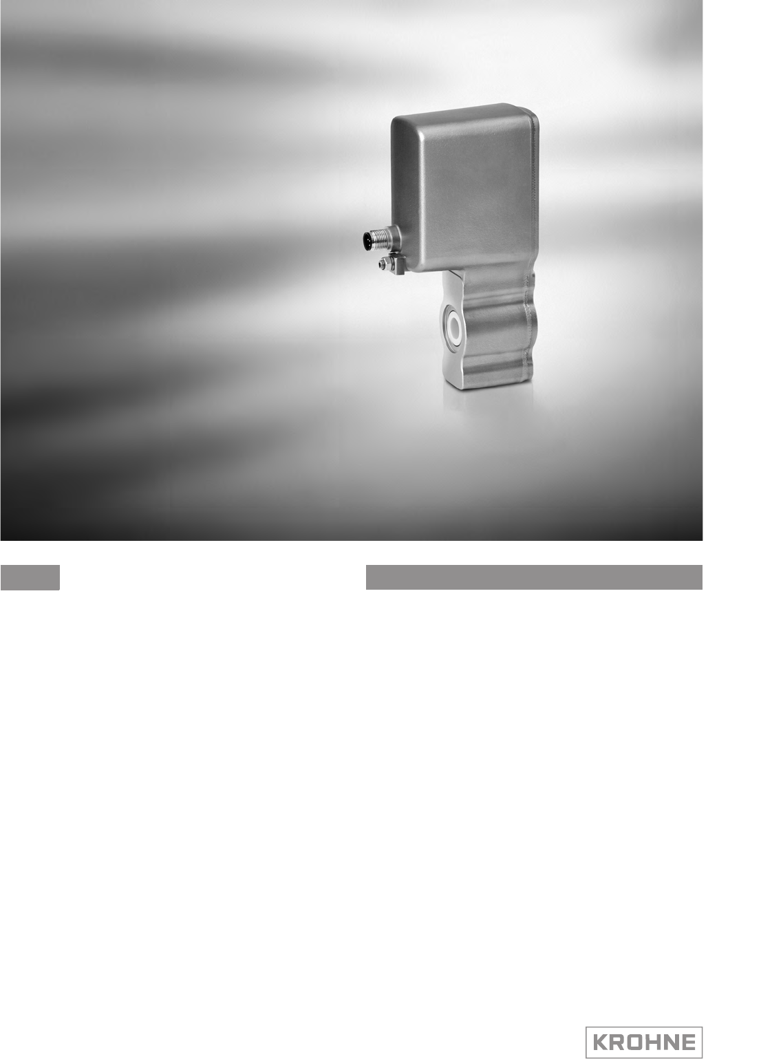
BATCHFLUX 5500 C Handbook Electromagnetic flowmeter for volumetric filling machines © KROHNE 05/2014 - 4000827703 - HB BATCHFLUX 5500 R03 en
: IMPRINT ::::::::::::::::::::::::::::::::::::::: All rights reserved. It is prohibited to reproduce this documentation, or any part thereof, without the prior written authorisation of KROHNE Messtechnik GmbH. Subject to change without notice. Copyright 2014 by KROHNE Messtechnik GmbH - Ludwig-Krohne-Str. 5 - 47058 Duisburg (Germany) 2 www.krohne.
CONTENTS BATCHFLUX 5500 C 1 Safety instructions 5 1.1 Intended use ..................................................................................................................... 5 1.2 Safety instructions from the manufacturer ..................................................................... 5 1.2.1 Disclaimer ............................................................................................................................... 5 1.2.2 Information concerning the documentation..........
CONTENTS BATCHFLUX 5500 C 6 Technical data 6.1 6.2 6.3 6.4 21 Measuring principle........................................................................................................ 21 Technical data................................................................................................................. 22 Dimensions and weights ................................................................................................ 26 Counter Flanges .................................................
SAFETY INSTRUCTIONS 1 BATCHFLUX 5500 C 1.1 Intended use The electromagnetic flowmeter is designed exclusively for measuring the volumetric flowrate of electrically conductive, liquid process products. Needed electrical conductivity for products: • > 5 µS/cm (except for water) • > 20 µS/cm (for water) 1.2 Safety instructions from the manufacturer 1.2.
1 SAFETY INSTRUCTIONS BATCHFLUX 5500 C 1.2.3 Warnings and symbols used Safety warnings are indicated by the following symbols. DANGER! This warning refers to the immediate danger when working with electricity. DANGER! This warning refers to the immediate danger of burns caused by heat or hot surfaces. DANGER! This warning refers to the immediate danger when using this device in a hazardous atmosphere. DANGER! These warnings must be observed without fail.
DEVICE DESCRIPTION 2 BATCHFLUX 5500 C 2.1 Scope of delivery INFORMATION! Inspect the packaging carefully for damages or signs of rough handling. Report damage to the carrier and to the local office of the manufacturer. INFORMATION! Do a check of the packing list to make sure that you have all the elements given in the order. INFORMATION! Look at the device nameplate to ensure that the device is delivered according to your order. Check for the correct supply voltage printed on the nameplate.
2 DEVICE DESCRIPTION BATCHFLUX 5500 C 2.2 Device description Your measuring device is supplied ready for operation. The factory settings for the operating data have been made in accordance with your order specifications. The following compact versions are available: • Version 1: converter directly mounted on cast sensor housing in size DN2.5..
DEVICE DESCRIPTION 2 BATCHFLUX 5500 C 2.3 Nameplate Figure 2-3: Nameplate 1 2 3 4 5 6 7 8 Name and address of the manufacturer Type designation, S/N nr and year of manufacturing Calibration and device data Tag number Marking ( ao. CE and 3-A logo ) Electrical values and software revision nr. Output data Additional info ( e.g. manufacturer website) 05/2014 - 4000827703 - HB BATCHFLUX 5500 R03 en www.krohne.
3 INSTALLATION BATCHFLUX 5500 C 3.1 General notes on installation INFORMATION! Inspect the packaging carefully for damages or signs of rough handling. Report damage to the carrier and to the local office of the manufacturer. INFORMATION! Do a check of the packing list to make sure that you have all the elements given in the order. INFORMATION! Look at the device nameplate to ensure that the device is delivered according to your order. Check for the correct supply voltage printed on the nameplate. 3.
INSTALLATION 3 BATCHFLUX 5500 C 3.4 General requirements INFORMATION! The following precautions must be taken to ensure reliable installation. • • • • Make sure that there is adequate space to the sides. Protect the signal converter from direct sunlight and install a sun shade if necessary. Support the pipeline on both side of the flowmeter. Do not expose the signal converter to intense vibration. The flowmeters are tested for a vibration level in accordance with IEC 60068-2-64.
3 INSTALLATION BATCHFLUX 5500 C 3.5 Installation conditions 3.5.1 Inlet and outlet 3 Figure 3-4: Inlet and outlet section 1 ≥ 5 DN 2 ≥ 2 DN 3 Drain valve (to empty pipeline) 3.5.2 Control valve Figure 3-5: Installation before control valve 3.5.3 Pump Figure 3-6: Installation after pump ∠α > 2° 1. Drain valve (to empty pipeline) 12 www.krohne.
INSTALLATION 3 BATCHFLUX 5500 C 3.5.4 Open feed or discharge Figure 3-7: Installation before an open discharge 3.5.5 Mounting position Figure 3-8: Installation in bending pipes ∠α ; > 2° 1. Drain valve ( to empty pipeline) CAUTION! Avoid draining or partial filling of the flow sensor. WARNING! Vertical down position only in conjunction of a control valve 05/2014 - 4000827703 - HB BATCHFLUX 5500 R03 en www.krohne.
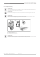
3 INSTALLATION BATCHFLUX 5500 C 3.5.6 Mounting 3.5.7 Installation location Figure 3-9: Installation location CAUTION! Mount the flow sensor in such a way that the electrode axis (X--------X) is approximately in a horizontal pipe run. 3.5.8 Flange deviation Figure 3-10: Mounting position and flange deviation 1 Lmax 2 Lmin CAUTION! Max. permissible deviation of pipe flange faces: Lmax - Lmin ≤ 0.5 mm / 0.02" 14 www.krohne.
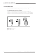
INSTALLATION 3 BATCHFLUX 5500 C 3.5.9 Temperatures Process temperature vs ambient temperature 1 Ambient temperature 2 Process temperature 3.5.10 Hot filling Installation position Figure 3-11: In case of hot fluids INFORMATION! Avoid installation near hot product tanks. If possible, try to insulate the flowmeter from radiant heat sources. CAUTION! On high temperature pipes and where temperatures exceed 100°C, provide facilities to compensate for longditudinal expansion of pipeline (due to heat-up).
4 ELECTRICAL CONNECTIONS BATCHFLUX 5500 C 4.1 Safety instructions DANGER! All work on the electrical connections may only be carried out with the power disconnected. Take note of the voltage data on the nameplate! DANGER! Observe the national regulations for electrical installations! WARNING! Observe without fail the local occupational health and safety regulations. Any work done on the electrical components of the measuring device may only be carried out by properly trained specialists.
ELECTRICAL CONNECTIONS 4 BATCHFLUX 5500 C 4.3 Electrical connection 4.3.1 Cable connector M12 - 5 pin All operating data for the BATCHFLUX 5500 C are preset at the factory. For changing the parameters and diagnostic purposes BATCHMon plus operation software can be used.
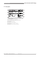
4 ELECTRICAL CONNECTIONS BATCHFLUX 5500 C 4.3.2 Cable connector M12 - 8 pin (with status output) The 8 pin electric connection has a status output. This status output, is configurable to customer specifications and offers either the flow direction (of the medium) or an error signal.
SERVICE 5 BATCHFLUX 5500 C 5.1 Spare parts availability The manufacturer adheres to the basic principle that functionally adequate spare parts for each device or each important accessory part will be kept available for a period of 3 years after delivery of the last production run for the device. This regulation only applies to spare parts which are subject to wear and tear under normal operating conditions. 5.
5 SERVICE BATCHFLUX 5500 C 5.3.2 Form (for copying) to accompany a returned device Company: Address: Department: Name: Tel. no.: Fax no.: Manufacturer's order no. or serial no.: The device has been operated with the following medium: This medium is: water-hazardous toxic caustic flammable We checked that all cavities in the device are free from such substances. We have flushed out and neutralized all cavities in the device.
TECHNICAL DATA 6 BATCHFLUX 5500 C 6.1 Measuring principle An electrically conductive fluid flows inside an electrically insulated pipe through a magnetic field. This magnetic field is generated by a current, flowing through a pair of field coils.
6 TECHNICAL DATA BATCHFLUX 5500 C 6.2 Technical data INFORMATION! • The following data is provided for general applications. If you require data that is more relevant to your specific application, please contact us or your local sales office. • Additional information (certificates, special tools, software,...) and complete product documentation can be downloaded free of charge from the website (Download Center).
TECHNICAL DATA 6 BATCHFLUX 5500 C Measuring accuracy Reference conditions Medium: water Inlet / outlet section: 10 DN / 5 DN Valve closing time variation: < 1 ms Flow velocity: 1 m/s, flow conditions similar to EN 29104 Operating pressure: 1 bar / 14.5 psi Error limits at reference conditions for tap water, 400 µS/cm, S/cm, 20°C 20 C / 68°F 68 F: Maximum measuring error DN2.5...6: v ≤ 1 m/s: ±0.4% of measured value + 1 mm/s v > 1 m/s: ±0.5% of measured value DN10...15: ±0.
6 TECHNICAL DATA BATCHFLUX 5500 C Operating conditions Temperature Process temperature Dependent on ambient temperature. See chapter "Temperatures". Cleaning temperature SIP: Maximum 1 hour at 150°C / +302°F CIP: Maximum 1 hour at 140°C / +284°F Shock ≤ 3 K/s Ambient temperature -40…+60°C / -40…+140°F Storage temperature -50…+70°C / -58…+158°F Pressure Ambient Atmospheric Process pressure up to 16 bar / 232 psi for DN10...15 up to 40 bar / 580 psi for DN2.5...6 / DN25...
TECHNICAL DATA 6 BATCHFLUX 5500 C Electrical connections Power supply 24 VDC ± 25% Power consumption ≤3W Switch on current ≤ 5 A (< 100 μs) at 24 VDC Voltage loss Possible for a maximum of 20 ms according to NAMUR NE21.
6 TECHNICAL DATA BATCHFLUX 5500 C 6.3 Dimensions and weights DN2.5...6 Figure 6-2: Dimensions 1 (Grounding) 2 M12; 5 - 8 pins connector Nominal size Dimensions [mm] Weight [kg] a b c d e f g h i DN2.5 50 156 206 6 → 2.5 44 88 141 128 54 1.5 DN4 50 156 206 7 → 3.2 44 88 141 128 54 1.6 DN6 50 156 206 9 → 4.8 44 88 141 128 54 1.
TECHNICAL DATA 6 BATCHFLUX 5500 C DN10...15 1 (Grounding) 2 M12; 5 - 8 pins connector Nominal size Dimensions [mm] Weight [kg] a b c d e f g h i DN10 50 140 179 10.5 → 8 45.4 60 106.5 88 54 1.4 DN15 50 140 179 14 → 12 45.4 60 106.5 88 54 1.4 Note on dimension d: As the diameter reduces to the middle, the diameter is specified for the inlet and for the middle Nominal size Dimensions [inches] Weight [lb] a b c d e f g h i 3/8" 1.97 5.51 7.05 0.41 → 0.
6 TECHNICAL DATA BATCHFLUX 5500 C DN25..40 Figure 6-3: Dimensions 1 (Grounding) 2 M12; 5 - 8 pins connector Nominal size Dimensions [mm] Weight [kg] a b c d e f g h i DN25 50 170 204 26 → 20 68 102 141 128 58 1.6 DN40 50 177 219 39 → 30 84 117 141 128 83 2.3 Note on dimension d: As the diameter reduces to the middle, the diameter is specified for the inlet and for the middle Nominal size Dimensions [inches] Weight [lb] a b c d e f g h i 1" 1.97 6.69 8.
TECHNICAL DATA 6 BATCHFLUX 5500 C 6.4 Counter Flanges The BATCHFLUX 5500 can be mounted between various types of counter flanges. Sizes of flanges DN a [mm] b [mm] c [mm] d [mm] O-ring Flange 1 2,5...10 * see table below * see table below * see table below Ø 30.4 Special Lring Flange 2 15 Ø 14.2 Ø 19.2 Ø 26.6 Ø 30.4 15.47 * 3.53 Flange 3 25 Ø 25 Ø 31.3 Ø 41.2 Ø 49.2 15.47 * 3.53 Size DN a1[mm] a2 [mm] b [mm] c [mm] 2,5 Ø 10 Ø 6.2 Ø 11.1 Ø 18.4 4 Ø 10 Ø 7.2 Ø 12.
6 TECHNICAL DATA BATCHFLUX 5500 C Reference to specific dimensions and drawing numbers Size DN Pcd [mm] D [mm] W [mm] Drawing number 2,5 Ø 56 Ø 68 14.5 4000587801 4 Ø 56 Ø 68 14.5 4000587807 6 Ø 56 Ø 68 14.5 4000587810 10 Ø 56 Ø 68 14.5 4000587815 15 Ø 56 Ø 68 14.9 4000587818 25 Ø 84 Ø 104 16.
NOTES 7 BATCHFLUX 5500 C 05/2014 - 4000827703 - HB BATCHFLUX 5500 R03 en www.krohne.
© KROHNE 05/2014 - 4000827703 - HB BATCHFLUX 5500 R03 en - Subject to change without notice. KROHNE product overview • • • • • • • • • • • • Electromagnetic flowmeters Variable area flowmeters Ultrasonic flowmeters Mass flowmeters Vortex flowmeters Flow controllers Level meters Temperature assemblies Pressure transmitters Analysis products Products and systems for the oil & gas industry Measuring systems for the marine industry Head Office KROHNE Messtechnik GmbH Ludwig-Krohne-Str.