BATCHFLUX 5500 C Quick Start Electromagnetic flowmeter for volumetric filling machines © KROHNE 05/2014 - 4003386301 - QS BATCHFLUX 5500 R03 en
CONTENTS BATCHFLUX 5500 C 1 Safety instructions 3 2 Installation 4 2.1 2.2 2.3 2.4 2.5 2.6 2.7 Scope of delivery............................................................................................................... 4 Device description ............................................................................................................ 5 Nameplate ........................................................................................................................ 5 Storage ........
SAFETY INSTRUCTIONS 1 BATCHFLUX 5500 C Warnings and symbols used DANGER! This information refers to the immediate danger when working with electricity. DANGER! These warnings must be observed without fail. Even partial disregard of this warning can lead to serious health problems and even death. There is also the risk of seriously damaging the device or parts of the operator's plant. WARNING! Disregarding this safety warning, even if only in part, poses the risk of serious health problems.
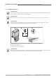
2 INSTALLATION BATCHFLUX 5500 C 2.1 Scope of delivery INFORMATION! Inspect the packaging carefully for damages or signs of rough handling. Report damage to the carrier and to the local office of the manufacturer. INFORMATION! Do a check of the packing list to make sure that you have all the elements given in the order. INFORMATION! Look at the device nameplate to ensure that the device is delivered according to your order. Check for the correct supply voltage printed on the nameplate.
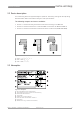
INSTALLATION 2 BATCHFLUX 5500 C 2.2 Device description Your measuring device is supplied ready for operation. The factory settings for the operating data have been made in accordance with your order specifications. The following compact versions are available: • Version 1: converter directly mounted on cast sensor housing in size DN2.5..
2 INSTALLATION BATCHFLUX 5500 C 2.4 Storage • • • • Store the device in a dry and dust-free location. Avoid lasting direct exposure to the sun. Store the device in its original packaging. Storage temperature: -50 ...+70°C / -58...+158°F 2.
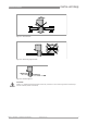
INSTALLATION 2 BATCHFLUX 5500 C Figure 2-4: Avoid vibrations Figure 2-5: Avoid strong magnetic fileds Figure 2-6: Horizontal piperun CAUTION! Install in a slightly descending pipe section to prevent air from collecting and to avoid faulty measurements (meter can drain). 05/2014 - 4003386301 - QS BATCHFLUX 5500 R03 en www.krohne.
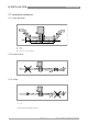
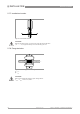
2 INSTALLATION BATCHFLUX 5500 C 2.7 Installation conditions 2.7.1 Inlet and outlet 3 Figure 2-7: Inlet and outlet section 1 ≥ 5 DN 2 ≥ 2 DN 3 Drain valve (to empty pipeline) 2.7.2 Control valve Figure 2-8: Installation before control valve 2.7.3 Pump Figure 2-9: Installation after pump ∠α > 2° 1. Drain valve (to empty pipeline) 8 www.krohne.
INSTALLATION 2 BATCHFLUX 5500 C 2.7.4 Open feed or discharge Figure 2-10: Installation before an open discharge 2.7.5 Mounting 2.7.6 Mounting position Figure 2-11: Installation in bending pipes ∠α ; > 2° 1. Drain valve ( to empty pipeline) CAUTION! Avoid draining or partial filling of the flow sensor. WARNING! Vertical down position only in conjunction of a control valve 05/2014 - 4003386301 - QS BATCHFLUX 5500 R03 en www.krohne.
2 INSTALLATION BATCHFLUX 5500 C 2.7.7 Installation location Figure 2-12: Installation location CAUTION! Mount the flow sensor in such a way that the electrode axis (X--------X) is approximately in a horizontal pipe run. 2.7.8 Flange deviation Figure 2-13: Mounting position and flange deviation 1 Lmax 2 Lmin CAUTION! Max. permissible deviation of pipe flange faces: Lmax - Lmin ≤ 0.5 mm / 0.02" 10 www.krohne.
INSTALLATION 2 BATCHFLUX 5500 C 2.7.9 Temperatures Process temperature vs ambient temperature 1 Ambient temperature 2 Process temperature 2.7.10 Hot filling Installation position Figure 2-14: In case of hot fluids INFORMATION! Avoid installation near hot product tanks. If possible, try to insulate the flowmeter from radiant heat sources. CAUTION! On high temperature pipes and where temperatures exceed 100°C, provide facilities to compensate for longditudinal expansion of pipeline (due to heat-up).
3 ELECTRICAL CONNECTIONS BATCHFLUX 5500 C 3.1 Safety instructions DANGER! All work on the electrical connections may only be carried out with the power disconnected. Take note of the voltage data on the nameplate! DANGER! Observe the national regulations for electrical installations! DANGER! For devices used in hazardous areas, additional safety notes apply; please refer to the Ex documentation. WARNING! Observe without fail the local occupational health and safety regulations.
ELECTRICAL CONNECTIONS 3 BATCHFLUX 5500 C 3.3 Electrical connection 3.3.1 Cable connector M12 - 5 pin All operating data for the BATCHFLUX 5500 C are preset at the factory. For changing the parameters and diagnostic purposes BATCHMon plus operation software can be used.
3 ELECTRICAL CONNECTIONS BATCHFLUX 5500 C 3.3.2 Cable connector M12 - 8 pin (with status output) The 8 pin electric connection has a status output. This status output, is configurable to customer specifications and offers either the flow direction (of the medium) or an error signal.
TECHNICAL DATA 4 BATCHFLUX 5500 C 4.1 Dimensions and weights DN2.5...6 Figure 4-1: Dimensions 1 (Grounding) 2 M12; 5 - 8 pins connector Nominal size Dimensions [mm] Weight [kg] a b c d e f g h i DN2.5 50 156 206 6 → 2.5 44 88 141 128 54 1.5 DN4 50 156 206 7 → 3.2 44 88 141 128 54 1.6 DN6 50 156 206 9 → 4.8 44 88 141 128 54 1.
4 TECHNICAL DATA BATCHFLUX 5500 C DN10...15 1 (Grounding) 2 M12; 5 - 8 pins connector Nominal size Dimensions [mm] Weight [kg] a b c d e f g h i DN10 50 140 179 10.5 → 8 45.4 60 106.5 88 54 1.4 DN15 50 140 179 14 → 12 45.4 60 106.5 88 54 1.4 Note on dimension d: As the diameter reduces to the middle, the diameter is specified for the inlet and for the middle Nominal size Dimensions [inches] Weight [lb] a b c d e f g h i 3/8" 1.97 5.51 7.05 0.41 → 0.
TECHNICAL DATA 4 BATCHFLUX 5500 C DN25..40 Figure 4-2: Dimensions 1 (Grounding) 2 M12; 5 - 8 pins connector Nominal size Dimensions [mm] Weight [kg] a b c d e f g h i DN25 50 170 204 26 → 20 68 102 141 128 58 1.6 DN40 50 177 219 39 → 30 84 117 141 128 83 2.3 Note on dimension d: As the diameter reduces to the middle, the diameter is specified for the inlet and for the middle Nominal size Dimensions [inches] Weight [lb] a b c d e f g h i 1" 1.97 6.69 8.
4 TECHNICAL DATA BATCHFLUX 5500 C 4.2 Counter Flanges The BATCHFLUX 5500 can be mounted between various types of counter flanges. Sizes of flanges DN a [mm] b [mm] c [mm] d [mm] O-ring Flange 1 2,5...10 * see table below * see table below * see table below Ø 30.4 Special Lring Flange 2 15 Ø 14.2 Ø 19.2 Ø 26.6 Ø 30.4 15.47 * 3.53 Flange 3 25 Ø 25 Ø 31.3 Ø 41.2 Ø 49.2 15.47 * 3.53 Size DN a1[mm] a2 [mm] b [mm] c [mm] 2,5 Ø 10 Ø 6.2 Ø 11.1 Ø 18.4 4 Ø 10 Ø 7.2 Ø 12.
TECHNICAL DATA 4 BATCHFLUX 5500 C Reference to specific dimensions and drawing numbers Size DN Pcd [mm] D [mm] W [mm] Drawing number 2,5 Ø 56 Ø 68 14.5 4000587801 4 Ø 56 Ø 68 14.5 4000587807 6 Ø 56 Ø 68 14.5 4000587810 10 Ø 56 Ø 68 14.5 4000587815 15 Ø 56 Ø 68 14.9 4000587818 25 Ø 84 Ø 104 16.
© KROHNE 05/2014 - 4003386301 - QS BATCHFLUX 5500 R03 en - Subject to change without notice. KROHNE product overview • • • • • • • • • • • • Electromagnetic flowmeters Variable area flowmeters Ultrasonic flowmeters Mass flowmeters Vortex flowmeters Flow controllers Level meters Temperature assemblies Pressure transmitters Analysis products Products and systems for the oil & gas industry Measuring systems for the marine industry Head Office KROHNE Messtechnik GmbH Ludwig-Krohne-Str.