© KROHNE 07/2000 Supplementary Installation and Operating Instructions BM 100 A KROHNE Messtechnik GmbH & Co. KG · Ludwig-Krohne-Str. 5 R D-47058 Duisburg Tel.: 0203-301 309 R Fax: 0203-301389 · e-mail: krohne@krohne.
Supplementary documentation BM 100 A with PROFIBUS-PA Contents: GENERAL.................................................................................................................................................................3 ITEMS INCLUDED WITH SUPPLY ...........................................................................................................................3 SOFTWARE HISTORY ............................................................................................................
Supplementary documentation BM 100 A with PROFIBUS-PA General These Instructions are supplementary to the ”Installation and Operating Instructions (Reference Manual) BM 100 A / BM 100EEX ”. The details given there, in particular the Safety Information, are valid and should be observed. These Supplementary Instructions provide only additional information for device operation and connection to a PROFIBUSPA fieldbus.
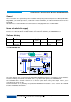
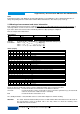
Supplementary documentation BM 100 A with PROFIBUS-PA 1.1 PROFIBUS-PA - Services The BM100A supports the following PROFIBUS services which have been defined in the PROFIBUS-PA-Profil V3.0: 1. 2. 3. 4. 5. 6. DDLM_Set_Slave_Add DDLM_Get_Cfg DDLM_Set_Prm DDLM_Chk_Cfg DDLM_Slave_Diag DDLM_Data_Exchange Those services are able to set the PROFIBUS station address (1), to configure the data telegramm for the cyclic data exchange (3/4).
Supplementary documentation BM 100 A with PROFIBUS-PA Units Independent from the units within the local operating display Level and Distance values will be transmitted in „m“ always. Depending from the volume table Volume will be transmitted as cubic metres (m3) or tons (t). 1.3 Meaning of measurement and status information Each configured measurement value is a 4 Byte Float Format according IEEE Standard 754 Short Real Number. A status byte follows each measurement value.
Supplementary documentation BM 100 A with PROFIBUS-PA Diagnostics If the device has detected an error, additional diagnostic information will be send to the master. The meaning of the additional information is described within the GSD file under UNIT_DIAG_BIT(i). 2. Electrical connection For a detailed description please check the Installation and Operating Instructions manual of the device. 2.
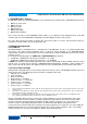
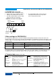
Supplementary documentation BM 100 A with PROFIBUS-PA 2.4 PROFIBUS-PA connection Connect the bus cable as shown in the figure. • Connect cable cores to terminals 4 and 4.1. • Polarity reversal will not have any effect. • The cable shield should be connected with minimum length to the ground PE. • The equipotential bonding conductor must be connected to the device, if necessary via the outer U-clamp ground terminal. PROFIBUS-PA with Current Output Current Fieldbus Output 5 6 Power Supply 4 4.1 4.